Multistage pump selection comes down to five numbers: the flow, the total head, the head each stage adds at that flow, the NPSH available at the first stage, and the highest pressure the casing will see. Divide the required head by the stage head to get the number of stages. Then check three things: the pump runs near its best efficiency point, the first stage will not cavitate, and suction pressure plus shut-off head stays within the casing rating. Shinjo's DF multistage pump covers 15–336 m³/h and 144–690 m. For very small flows at high head, a partial emission pump is often the better fit.
State the minimum, normal and maximum flow, and how long the pump runs at each. If two pumps share a header, work out the real combined demand rather than adding up the maximum of every user. Say whether a standby pump must carry the full duty alone.
Record the liquid's temperature, density, viscosity and vapor pressure as well. Water-based pump curves do not apply directly to viscous oils, and abrasive solids rule out most multistage pumps, which have close running clearances.
Do not add a margin to every number. A safety factor on flow, another on friction losses and a third on head lead to a pump that spends its life throttled, far from its best efficiency point.
For a pump moving liquid between two vessels, the required head is:
H = Δz + Δp ÷ (ρ × g) + hL
Δz is the elevation difference, Δp the pressure difference between the vessels, ρ the liquid density, g gravity and hL the friction loss in pipes, fittings, valves and equipment. For large tanks, the velocity difference is negligible.
Example: water at 20 °C is pumped from an open tank to a vessel at 2.2 MPa gauge, 25 m higher, with 20 m of friction loss at 28 m³/h:
H = 25 + 2,200,000 ÷ (998 × 9.81) + 20 ≈ 25 + 224.7 + 20 ≈ 270 m
Two common mistakes: adding the discharge pressure again when it is already counted in Δp, and forgetting to subtract the pressure in a pressurized suction vessel. For more on the terms, see total head and total dynamic head and pump head loss.
In a multistage pump, the impellers work in series. The same flow passes through every stage, and their heads add up. So the number of stages is roughly the required head divided by the head of one stage at the duty flow.
Shinjo's DF46-50 adds 57.5 m per stage at 28 m³/h. For the 270 m example: 270 ÷ 57.5 = 4.7, so five stages are needed. The published data for this model at 28 m³/h:
| Stages | Head at 28 m³/h | Shaft power | Motor |
|---|---|---|---|
| 3 | 172.5 m | 24.8 kW | 37 kW |
| 4 | 230 m | 33.1 kW | 55 kW |
| 5 | 287.5 m | 41.4 kW | 55 kW |
| 6 | 345 m | 49.6 kW | 75 kW |
Five stages give 287.5 m, which is 17.5 m more than needed. In practice, the pump will run slightly further out on its curve, where the system curve crosses it. Alternatively, the impellers can be trimmed, or a variable-frequency drive can reduce speed. Do not add a sixth stage "for margin". It adds 57.5 m of head that would be burned off in a throttling valve, plus about 8 kW of shaft power.
You can check the shaft power from the head, flow and efficiency (53% for this model):
P = ρ × g × Q × H ÷ η = 998 × 9.81 × (28 ÷ 3,600) × 287.5 ÷ 0.53 ≈ 41.3 kW
Select the motor for the highest power anywhere on the allowable operating range, not just at the duty point. Read the pump performance curve out to maximum flow and, for liquids heavier than water, scale the power with density.
Only the first impeller sees the suction conditions, so the first stage decides whether the pump cavitates. Adding stages raises the discharge pressure but does nothing for the suction.
Manufacturers publish NPSH required as NPSH3: the suction head at which cavitation has already cut the first-stage head by 3%. The pump is cavitating at that point, so NPSH available must be higher, with a margin. Calculate NPSH available at the lowest liquid level, the highest temperature and the lowest suction vessel pressure together, using absolute pressures. Hot water is the usual problem. Its vapor pressure rises steeply, which is why feed pumps on deaerators sit far below the tank.
If NPSH is short, raise the tank, enlarge and shorten the suction pipe, cool the liquid, choose a lower-speed pump, or add a low-head booster pump in front.
The casing must hold the highest pressure it can ever see. That is the maximum suction pressure plus the pump's shut-off head, at maximum speed and maximum liquid density. It is not just the discharge pressure at the duty point. Compare it with the allowable working pressure of the casing, nozzles and seal at operating temperature. The hydrostatic test pressure, usually 1.5 times the allowable working pressure, is a factory test, not an operating limit.
Check the inlet pressure as well. The DF pump is rated for an inlet pressure below 0.6 MPa. That matters when it takes suction from a pressurized vessel or runs in series behind another pump.
Every impeller pushes the rotor toward the suction end, and in a multistage pump these forces add up. Ring-section multistage pumps usually balance them with a balance disc or drum and a thrust bearing. Balance devices rely on close clearances, so abrasive particles wear them and let the rotor shift. Keep the liquid clean, and fit a suction strainer where needed.
Ask the supplier what pressure the shaft seal sees. It depends on the design and is not always full discharge pressure.
At low flow, most of the motor's power turns into heat in a small amount of liquid, and the liquid recirculates inside the impellers. Ask for the minimum continuous flow. If the process can demand less, fit a minimum-flow bypass that returns liquid to the suction tank, not directly to the pump inlet.
- Never run dry. The balance device and wear rings have close clearances and seize without liquid.
- Never run below minimum flow or against a closed discharge valve for long.
- Do not exceed the inlet pressure rating, 0.6 MPa on the DF pump.
- Fill and vent the pump before starting. Trapped air in the upper stages causes dry running.
- Keep abrasive solids out. They wear the clearances that hold the rotor in place.
| Pump | Flow | Head | Construction and limits |
|---|---|---|---|
| DF single-suction multistage | 15–336 m³/h | 144–690 m | Cast iron, cast steel or stainless steel; −20 to 105 °C; inlet pressure below 0.6 MPa; 2,950 or 1,480 rpm |
| Stainless steel multistage | 0.3–10 m³/h | 14.6–198 m | Stainless steel casing, impeller and shaft; tungsten carbide bearings and seal |
| Partial emission pump | 0.1–15 m³/h | 16–120 m | Single stage, 0.75–37 kW |
For small clean-water duties of 2–32 m³/h, the compact cast iron multistage pump has stainless steel impellers and inner parts in a cast iron frame, with motors of 0.37–3 kW. It handles water from −15 to 70 °C, or up to 120 °C in its hot-water version.
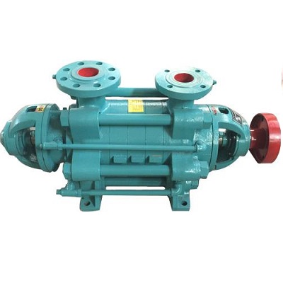
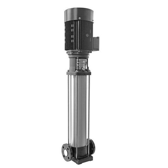
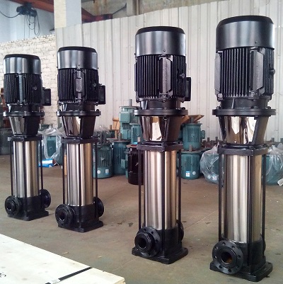
Choose the material from the liquid. Cast iron suits clean, cold water at moderate pressure. Cast steel suits higher pressures and hot water up to the DF's 105 °C limit. Stainless steel suits corrosive liquids, demineralized water, which attacks cast iron, and hygienic duties.
A multistage pump sized for a very small flow ends up with small, inefficient stages, or with a larger pump running far below its best efficiency point and relying on a bypass. For flows up to 15 m³/h and heads up to 120 m, Shinjo's high head partial emission pump reaches the head in a single stage. Its data table lists motor sizes for liquid densities of 1.0, 1.4 and 1.86, which shows how strongly power depends on density. Compare both options on curves, power and NPSH before deciding. For more on general selection, see how to select a centrifugal pump.
- Minimum, normal and maximum flow, and the running time at each.
- Total head, or the system details to calculate it: elevations, vessel pressures and pipe layout.
- Liquid, temperature, density, viscosity and vapor pressure.
- Suction conditions: tank level, suction pressure and NPSH available.
- Maximum suction pressure, for the casing pressure check.
- Material requirements, power supply and any required standard, such as API 610 or ISO 9906 test grades.
Need a pump for a high-head duty? Send your duty data to SHINJO and we will select the stages, material and motor for you. See our full range of multistage pumps.
No. Stages in series add head while carrying the same flow. The operating flow is where the pump curve crosses the system curve, so more stages shift that point only because the head rises.
Divide the required total head by the head of one stage at the duty flow, then round up. For example, 270 m at 28 m³/h with a DF46-50, which adds 57.5 m per stage, needs five stages. Then check efficiency, power and NPSH for that selection.
Because cavitation happens at the first impeller, which sees only the suction conditions. Extra stages raise the discharge pressure, not the suction pressure. Improve NPSH available, or choose a pump with a lower NPSH requirement.
The DF pump is rated for an inlet pressure below 0.6 MPa. Check this when it takes suction from a pressurized vessel or runs in series behind a booster pump.
When the flow is very small compared with the head: up to about 15 m³/h at heads up to 120 m. A single-stage partial emission pump then avoids a multistage pump running far below its best efficiency point.
