Centrifugal pump maintenance that really extends pump life comes down to two habits: routine checks while the pump runs, and a precision rebuild when it is opened. In a rebuild, the wet end decides the result. New bearings and a new seal will not last if the impeller, casing and stuffing box cover go back with worn faces and open clearances. This guide follows Crane Engineering's precision maintenance video and adds the routine checks, wear limits and fits you need to bring a pump back to as-new condition.
Joe Frank of Crane Engineering inspects the wet end of a back pull-out end-suction pump. Video: Crane Engineering on YouTube (10:20).
What the video covers:
- 0:42 Casing inspection: face grooves, gasket area and cutwater
- 1:32 Impeller inspection: vanes, back pump-out vanes and fits
- 2:07 Stuffing box cover inspection
- 3:00 Wear limits for reusing each part
- 4:22 Impeller clearance, thrust and seal life
- 6:43 Worn parts from real pumps
- 8:32 An abrasive wear example
- 9:22 Wear rings on split-case pumps
Most pump failures give warning first: noise, heat, leakage or vibration. Routine centrifugal pump maintenance catches them while the fix is still cheap. The schedule below draws on a widely used preventive maintenance guide for centrifugal pumps and on the U.S. Department of Energy's pumping system tip sheets. Adapt the intervals to your duty, and follow your pump manual where it differs.
| Interval | Check | What to look for |
|---|---|---|
| Daily | Noise | A gravel-like rattle at the suction usually means cavitation; a rising whine or rumble points to the bearings |
| Daily | Bearing temperature | Feel or measure every bearing and compare with earlier readings, not just with a limit |
| Daily | Bearing oil and leaks | Water or discoloration in the oil; oil leaking at gaskets |
| Daily | Seal and packing leakage | Mechanical seal leakage within the maker's limit; packing leakage typically 2–60 drops per minute |
| Daily | Seal flush and cooling | Flush flow or flush line temperature; cooling water flowing through jackets and coolers |
| Monthly | Lubrication | Top up oil, clean oiler bulbs and sight glasses, and check the oil level against the shaft centerline |
| Monthly | Guards and housekeeping | Guards in place, debris cleared from the bearing bracket, drain holes open |
| Every 6 months | Standby pumps | Turn the shaft by hand several turns to coat the bearings with oil; protect exposed machined surfaces from rust |
| Yearly | Alignment and coupling | Check alignment with a dial indicator, allowing for thermal growth; inspect the coupling for wear and cracks; check the axial float |
| Continuous trend | Vibration and performance | Rising vibration, or falling flow and head at the same speed, means wear inside the pump |
Do not keep tightening packing to stop a leak. Overtightened packing wears the shaft sleeve and raises power consumption. If it has to be tightened excessively, replace it.
A centrifugal pump relies on small gaps between rotating and stationary parts to keep high-pressure liquid at the discharge from flowing back to the suction. As those gaps wear open, more liquid recirculates inside the pump. The pump keeps running, but it delivers less flow and head for the same power.
The losses are significant. The U.S. Department of Energy notes that erosion of wear rings and the rotor can reduce a pump's wire-to-water efficiency by 10% or more. In a worked example by pump engineer Lev Nelik, doubling the wear ring clearance on a double-suction pump rated at 8,000 gpm and 400 ft (about 1,800 m³/h at 122 m) lets about 4% of the rated flow leak back. At roughly 900 hp, that wastes about 27 kW, or around $23,600 a year at $0.10/kWh in continuous service.
Energy is only part of the cost. As the video explains, open clearances also raise thrust loads and seal chamber pressure, which shortens bearing and seal life.
In a back pull-out end-suction pump, the wet end has three parts: the casing (volute), the impeller and the stuffing box cover, also called the seal chamber cover or back plate. When a back pull-out assembly is exchanged, the casing usually stays bolted into the piping, so it is easy to skip. Inspect it anyway: it is often the oldest part of the pump.
- Grooves across the face that runs next to the impeller.
- Cracks, irregularities or washouts at the gasket surface.
- The cutwater. It should be smooth and straight across; a worn or washed-out cutwater lets more liquid recirculate around the volute.
- Grooves or general wear on the face that runs next to the casing.
- Bent vanes.
- The back pump-out vanes: their height and whether the edges are still sharp.
- The threads, and the face that seats against the shaft sleeve.
- Wear, grooves or pitting on the face that runs next to the impeller.
- The gasket surface against the casing.
- The bore where the shaft sleeve passes through.
- The face where the mechanical seal mounts.
- The register that locates the cover on the frame adapter.
The video gives clear limits for reusing wet-end parts on an end-suction pump. Lay a straight edge across each face to judge the depth of grooves and general wear.
| Part | Area | Replace when |
|---|---|---|
| Casing | Face next to the impeller | Grooves or irregularities deeper than 1/8 in (3.2 mm) |
| Impeller | Face next to the casing | Wear or grooves deeper than 1/16 in (1.6 mm) |
| Impeller | Vanes | Any vane is bent |
| Impeller | Back pump-out vanes | Worn by more than 1/32 in (0.8 mm), or edges rounded by abrasion |
| Stuffing box cover | Face next to the impeller | Grooves or general wear of 1/8 in (3.2 mm) or more |
Where your pump manufacturer gives tighter limits, use those. A part just inside the limit can go back in, but expect some extra leakage and a small loss of efficiency. The video shows a stuffing box cover with grooves just under 1/8 in that falls into exactly this category, and a suction side plate with grooves deep enough that it should not be reused.
Open and semi-open impellers run with a small axial gap to the casing. For the mid-size ANSI pump in the video, the operating manual calls for 0.008 in (0.20 mm) at service temperatures of 200 °F (93 °C) or below. With the impeller set there, the gaps in front of and behind the impeller typically add up to 0.060–0.085 in (1.5–2.2 mm) between the casing and the stuffing box cover.
The right setting depends on temperature. Parts grow as they heat up, so hot service needs a larger cold setting. One of the casings in the video came from a pump set at the standard 0.008 in while the process ran above 300 °F (about 150 °C). The impeller grew into the casing, the two rubbed, and the casing was heavily worn.
On pumps that adjust with jack bolts and locking bolts on the bearing housing, the usual procedure is:
- Lock out the driver, then remove the coupling guard and the coupling.
- Mount a dial indicator with its button on the end of the shaft.
- Back out the jack bolts, then tighten the locking bolts evenly until the impeller just touches the casing. Zero the indicator.
- Back off the locking bolts, then tighten the jack bolts evenly to push the housing out until the indicator shows the specified clearance.
- Tighten the locking bolts evenly while the jack bolts hold the setting, and check that the shaft turns freely by hand.
Some designs adjust with shims or an adjusting nut instead. Follow the manual for your pump. For more on the impeller types themselves, see open, semi-open and closed impellers.
Because an open impeller is adjustable, it is tempting to keep moving it toward the casing as the faces wear. That restores the front clearance, but the impeller moves the same distance away from the stuffing box cover, and the back gap grows. The back pump-out vanes are designed to work across a small back gap, so a wider one causes trouble.
- Higher thrust. The back pump-out vanes lower the pressure behind the impeller and with it the axial thrust on the shaft. With a wide gap they lose effect, and very open clearances can lead to thrust bearing failures.
- Solids reach the seal. The pump-out vanes no longer push particles outward, so more solids get into the seal area.
- Higher stuffing box pressure. Packing leaks more heavily and mechanical seals fail sooner.
Once the faces are worn past their limits, the fix is to restore or replace the parts, not to keep resetting the impeller.
Closed impellers, including the double-suction impellers in split-case pumps, seal against the casing with wear rings rather than an axial gap. The video notes that on split-case pumps the total clearance between the impeller ring and the casing ring is typically only 0.020–0.040 in (0.5–1.0 mm), depending on pump size and ring material. Wear rings cannot be adjusted, so the only cure for wear is new rings.
One fits-and-clearances checklist based on Hydraulic Institute standards gives this guide for the new diametral clearance between impeller ring and casing ring, for rings up to 12 in (305 mm) in diameter:
Clearance = 0.010–0.012 in + 0.001 in per inch of ring diameter
Example, 8 in (203 mm) ring: 0.018–0.020 in (0.46–0.51 mm)
Add 0.005 in (0.13 mm) for materials that tend to gall, such as stainless steel.
- When to renew them. The same checklist says to renew the rings when the clearance reaches twice the original value. Some manufacturers replace them sooner, when the clearance has grown by 40%.
- Rear rings. Excessive clearance at the rear rings raises axial thrust and can damage the thrust bearing.
- Fitting. Rings are pressed on with 0.002–0.003 in (0.05–0.08 mm) interference and locked with dowels or tack welds in at least two places. Do not bore out a casing ring seat by more than 3% of its original diameter.
A precision rebuild also restores the fits that keep the rotor running true. The values below come from the same checklist. Use the pump maker's figures where they differ.
| Fit | Inches | Millimeters |
|---|---|---|
| Ball bearing bore to shaft | 0.0001–0.0007 interference | 0.003–0.018 interference |
| Ball bearing outside diameter to housing | 0.0001–0.001 clearance | 0.003–0.025 clearance |
| Shaft sleeve to shaft | 0.001–0.0015 clearance | 0.025–0.038 clearance |
| Impeller to shaft | Metal to metal, up to 0.0005 clearance | Metal to metal, up to 0.013 clearance |
| Coupling hub to shaft | Metal to metal, up to 0.0005 clearance | Metal to metal, up to 0.013 clearance |
| Throat bushing to shaft | 0.015–0.020 clearance | 0.38–0.51 clearance |
| Seal gland throttle bushing to shaft | 0.018–0.020 clearance | 0.46–0.51 clearance |
| Seal gland pilot to stuffing box | 0.002–0.004 clearance | 0.05–0.10 clearance |
| Casing, cover and bearing housing alignment | 0.004 maximum | 0.10 maximum |
| Mechanical seal faces | Flat within 3 helium light bands | About 0.0009 |
The last end-suction example in the video is a back pull-out assembly from abrasive service, and every wet-end surface shows it. The vanes and the impeller face are worn and uneven. The back pump-out vanes are nearly gone. The stuffing box cover is cupped from the center outward, and the casing has heavy washout near the cutwater.
In abrasive duty, plan for faster wear:
- Shorten the inspection interval and trend performance, so parts are replaced before they pass their limits.
- Keep the pump near its best efficiency point. At low flow, liquid recirculates inside the pump and wears it faster.
- Choose harder materials, or a pump designed for solids, such as a slurry pump.
- Protect the mechanical seal from solids with a suitable flush, and keep the back pump-out vanes in good condition.
A rebuild makes sense when the casing is sound and the wet-end parts can be brought back within limits. Consider a new pump or a new back pull-out assembly instead when:
- The casing is cracked, washed out at the gasket face or grooved beyond 1/8 in, and cannot be repaired by building up and re-machining.
- The impeller has bent vanes or wear beyond the limits, and the parts would cost close to a new assembly.
- The pump runs far from its best efficiency point. A pump that does not suit its duty will keep wearing the same way, so check the operating point on the pump performance curve and reselect if needed. Our guide on how to select a centrifugal pump covers the process.
- Failures keep returning at short intervals even after careful rebuilds. Find the root cause first, whether it is the operating point, the piping or the liquid.
If you are sourcing a replacement, see our comparison of centrifugal pump suppliers in China.
The pump layout decides how quickly and accurately centrifugal pump maintenance can be done.
- IS horizontal clean water centrifugal pump. Built to ISO 2858 dimensions with a back pull-out layout: the casing and cover separate behind the impeller. Remove the coupling spacer and the rotor comes out without disturbing the casing, the suction and discharge piping or the motor. Flows up to 400 m³/h and heads up to 125 m, for clean water up to 80 °C.
- IH stainless steel chemical centrifugal pump. The same back pull-out layout for corrosive liquids.
- Horizontal split-case pump. The casing splits along the shaft line, so the upper half lifts off for access to the rotor and wear rings while the pipework stays connected.
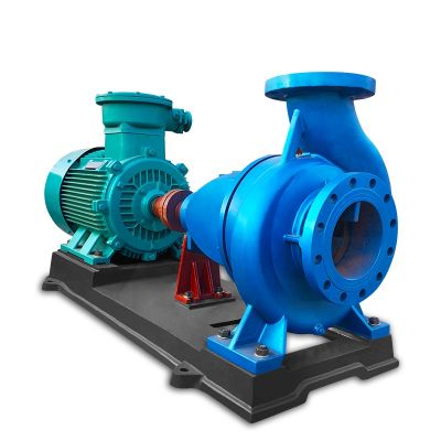
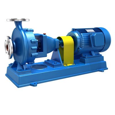
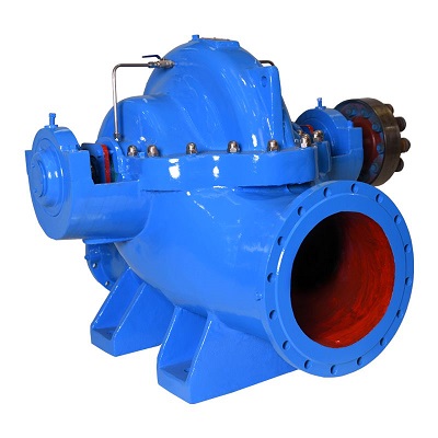
Shinjo supports its pumps with spare parts, remote technical support and video installation guidance.
Planning a pump rebuild or a replacement? Send SHINJO the pump model, the duty and photos of the worn parts, and we will recommend spare parts or a replacement pump. See our full ranges of centrifugal pumps and split-case pumps.
Check noise, bearing temperature and leakage daily, lubrication monthly, and alignment and the coupling once a year. Open the pump for a rebuild when trends show falling performance, rising vibration or repeated seal leaks, rather than on a fixed calendar.
Use the value in the pump's operating manual for your service temperature. For example, the video quotes 0.008 in (0.20 mm) for a mid-size ANSI pump at 200 °F (93 °C) or below. Hot service needs a larger cold setting to allow for thermal growth.
A common rule is to renew them when the clearance reaches twice its original value. Some manufacturers replace them sooner, when the clearance has grown by 40%. Wear rings cannot be adjusted, so new rings are the only way to restore the clearance.
Check the back clearance. If the impeller was moved toward the casing to make up for front wear, the gap to the stuffing box cover grows. The back pump-out vanes then stop clearing solids from the seal area and the stuffing box pressure rises. Worn pump-out vanes have the same effect.
Only within limits. In the video, casing grooves up to 1/8 in (3.2 mm) and impeller face wear up to 1/16 in (1.6 mm) are acceptable, while any bent vane means a new impeller. Parts close to the limit still work, but with some extra leakage and lower efficiency.
Run it near its best efficiency point, keep lubrication and alignment in order, and trend vibration and performance. When the pump is opened, rebuild it to as-new clearances instead of replacing only the bearings and the seal.
