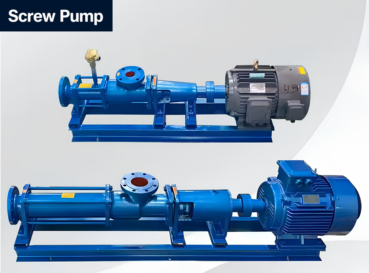
A screw pump must be selected around the fluid, required flow, differential pressure and suction condition, not appearance or family name alone.
A screw pump is a rotary positive-displacement pump that moves fluid through enclosed spaces created by one or more helical elements. That definition sounds straightforward, but the name covers several machines that should not be selected as if they were interchangeable. A progressive-cavity single-screw pump moves sludge, slurry and viscous liquids through cavities between an eccentric rotor and a stator. Twin-screw and three-screw pumps use different rotor arrangements and are often chosen for oil, multiphase, hygienic or lubricating-fluid duties. An Archimedes screw lifts water in an open or partly open channel, while a dry screw vacuum pump compresses gas rather than transferring process liquid.
This guide focuses on industrial liquid-handling screw pumps, with extra attention to the progressive-cavity single-screw design represented in Shinjo's current range. It explains how the pump produces flow, what each part does, where the main pump types fit, how to choose materials and speed, and what information a manufacturer needs before giving a defensible quotation.
Safety note: A screw pump is a positive-displacement machine. A blocked or isolated discharge can produce a rapid pressure rise unless the system has suitable overpressure protection. Rotating equipment, pressurised fluid, chemicals and hot media can also cause serious injury. Selection, guarding, installation and maintenance should be reviewed by qualified personnel and follow the pump manual, plant procedure and applicable code.
An industrial screw pump captures a known volume of fluid and carries it from suction to discharge as a screw or rotor turns. Because the pump displaces volume rather than adding velocity and converting it into pressure as a centrifugal pump does, its flow is primarily related to displacement and speed. Actual flow is lower than theoretical displacement because some liquid slips backward through clearances or sealing lines, especially as differential pressure rises or viscosity falls.
The system creates the pressure. The pump supplies flow against the resistance in the pipe, equipment and elevation. This distinction matters when a buyer asks for "a 6 bar pump." Six bar does not describe the flow, viscosity, suction condition, materials or motor torque. The supplier still needs the complete duty.
| Term | Basic mechanism | Typical strengths | Do not confuse it with |
|---|---|---|---|
| Single-screw or progressive-cavity pump | Eccentric metal rotor turns inside a double-helix stator, creating sealed progressing cavities | Viscous, solids-bearing and shear-sensitive liquids | Archimedes water-lifting screw |
| Twin-screw pump | Two matched screws form moving chambers; designs may use timing gears to prevent rotor contact | High flow, oil, multiphase or hygienic duties depending on design | Two-stage progressive-cavity pump |
| Three-screw pump | One driving screw and two idler screws move clean lubricating liquid axially | Fuel, lube oil and hydraulic service | Solids-handling slurry pump |
| Archimedes screw | Large inclined helix lifts water or solids in an open trough | Low-head drainage, irrigation and wastewater lifting | Enclosed process screw pump |
| Dry screw vacuum pump | Non-contacting screw rotors trap and compress gas | Industrial vacuum generation | Liquid-transfer screw pump |
This article uses "single-screw pump" and "progressive-cavity pump" for the rotor-stator machine. Industry naming varies, so a quotation should identify the actual construction rather than relying on the family name alone.
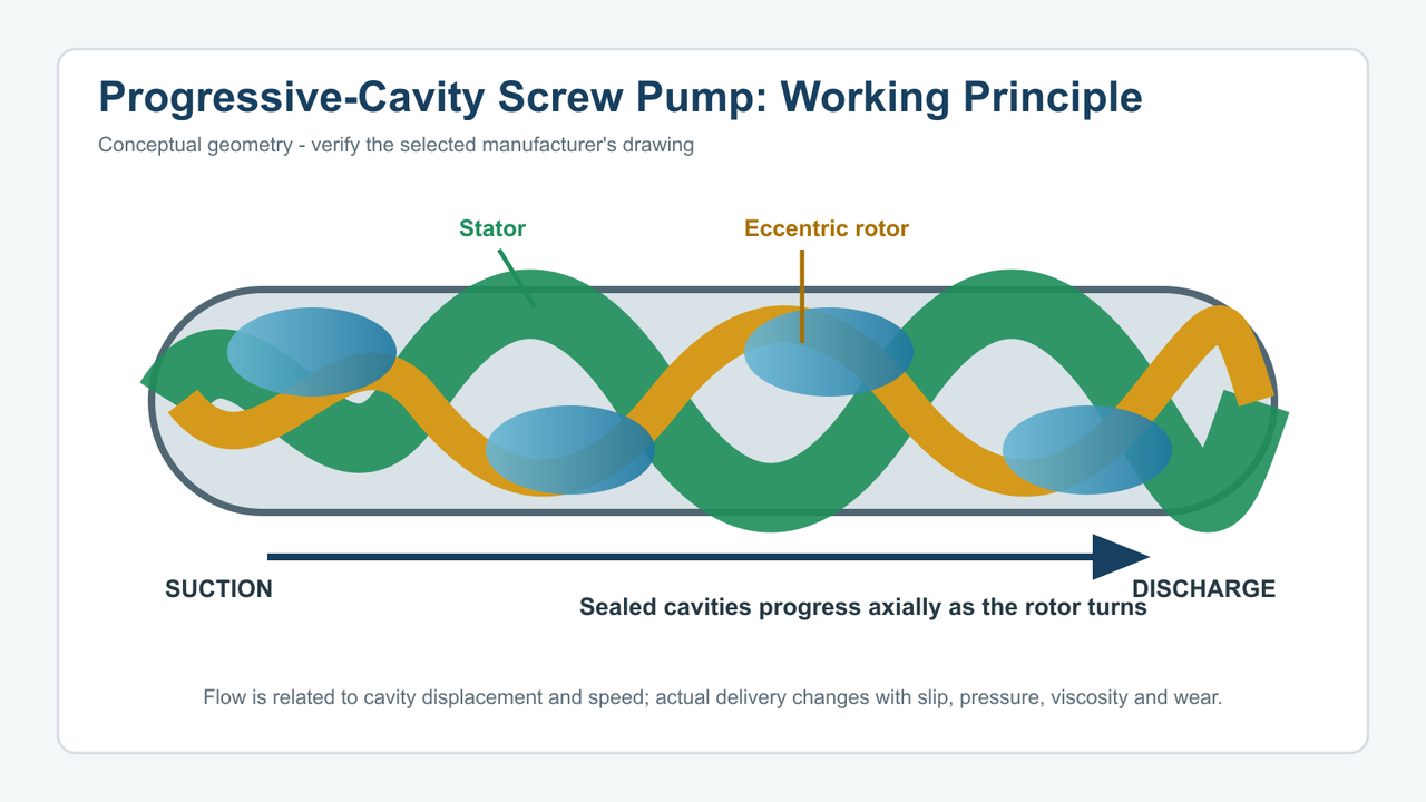
Conceptual working-principle diagram: sealed cavities progress from suction to discharge as the eccentric rotor turns. Verify geometry and rotation against the selected manufacturer's drawing.
In a progressive-cavity pump, the rotor is usually a single external helix. The stator has a corresponding double internal helix, creating a cylindrical cavity around the rotating screw. Their geometries create a series of sealed cavities. As the rotor turns eccentrically inside the stator, each fluid chamber progresses from the suction side to the discharge side without changing its general shape.
The operating sequence is:
- Fluid enters at the suction casing and fills an open cavity between the rotor and stator.
- Rotor movement closes that cavity against adjacent sealing lines.
- As the screws rotate, the cavity moves axially toward the discharge.
- New cavities form behind it, producing continuous displacement and setting the flow rate.
- The cavity opens into the discharge casing and releases the fluid into the system.
Because the rotor does not reverse direction like a reciprocating piston, the progressing cavities support continuous flow and non-pulsating flow, unlike diaphragm pumps. "Low pulsation" does not mean perfectly constant flow under every condition. Inlet starvation, gas pockets, worn sealing lines, excessive differential pressure and unstable speed can still disturb delivery.
The eccentric motion is the defining feature. An eccentric screw pump is also called a progressing cavity pump in some sources. The rotor does not simply spin around the pump centreline. Its axis moves around the stator axis while the rotor turns, and the drive train must accommodate that movement through a flexible shaft, coupling rod and universal joints or another suitable arrangement; this screw pump design is a positive displacement type that relies on a rotating screw advancing sealed cavities through the stator.
Several design features follow from this geometry:
- Positive displacement: each rotor revolution transports an approximate cavity volume, so a variable-frequency drive can regulate flow over a model-specific speed range.
- Sealing lines: contact or close sealing between rotor and stator allows the pump to build differential pressure in stages. Wear or chemical swelling changes those sealing lines and therefore changes slip, torque and flow.
- Gentle axial movement: the fluid is transported in cavities rather than thrown from an impeller tip, making the design useful for some shear-sensitive emulsions, food products, food processing duties and polymers.
- Solids passage: cavities can move suspended particles and short fibres when their size, concentration and abrasiveness remain within the selected model's limits.
- Self-priming capability: many progressive-cavity pumps can evacuate air and lift liquid under suitable conditions, but priming capability is model- and speed-dependent and does not permit prolonged dry running.
Theoretical flow rate is approximately displacement per revolution multiplied by rotational speed. Actual flow also depends on slip. Higher differential pressure tends to increase internal leakage from discharge toward suction. Low-viscosity liquid slips more readily than a thick liquid through the same sealing path, so slip usually changes less with high viscosity fluids through the same clearance. Wear increases leakage area and can reduce capacity at the original speed.
A VFD is useful because it can vary flow without throttling a positive-displacement pump. However, lower speed is not automatically harmless. The drive must maintain sufficient cooling, the pump must remain within its controllable range and the inlet must fill each cavity. At high speed, viscous fluids or solids-laden liquid may not enter quickly enough, leading to starvation, cavitation-like noise, vibration and rapid stator damage. In some duties, a larger pump running more slowly is preferable to chasing higher flows by increasing speed.
Pressure develops when the downstream system resists flow. The number of pressure stages and the allowable pressure per stage are design limits. Adding stages may increase allowable differential pressure, but it does not mean an operator should dead-head the pump.
Required torque rises with differential pressure, displacement, mechanical friction and fluid behaviour. Cold startup can be a severe case because viscosity may be much higher than at normal operating temperature. Stator interference and elastomer swelling can add torque. The motor and gearbox should therefore be checked against the worst credible operating condition, not only warm steady-state duty.
The pumped liquid commonly lubricates and cools the rotor-stator interface. When the inlet runs empty, friction can heat an elastomer stator rapidly. The result may be glazing, cracking, tearing, debonding or permanent dimensional change. A few seconds may be significant for some combinations, while other designs tolerate limited dry exposure; the manufacturer must define the limit.
Useful protection can include a level switch, flow switch, suction pressure transmitter, motor power monitor, stator-temperature sensor or timed shutdown logic. The right device depends on the liquid and failure mode. "Self-priming" must never be interpreted as "safe to run dry indefinitely."
Understanding the parts makes a quotation easier to judge. Every component below changes either hydraulic performance, material compatibility, maintenance or safety.
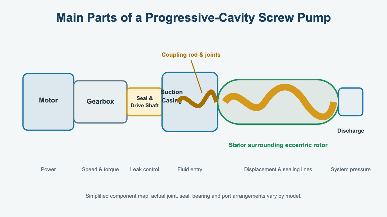
Simplified component map for purchasing discussions. Joint, seal, bearing and port arrangements vary by manufacturer and model.
The rotor is the helical rotating element. It may be made from alloy or stainless steel and may use hard coating for wear resistance. The correct choice depends on corrosion, abrasion, cleanability and the stator compound. Ask for base material, surface treatment, hardness where relevant and whether the rotor can be refurbished.
A worn rotor reduces sealing effectiveness even if the stator is new. Installing a fresh stator around a deeply scored or undersized rotor may restore high friction without restoring full capacity.
The stator forms the stationary helical cavity and is often the most application-sensitive wear part. Elastomer options may include natural rubber, nitrile, EPDM, FKM or other compounds, but names alone do not prove compatibility. Chemical concentration, oil content, pH, cleaners and operating temperature all matter.
An incompatible stator may soften, harden, swell or shrink. Swelling can raise starting torque and current; shrinkage or wear can increase slip and reduce pressure capability. Give the supplier an exact fluid composition and cleaning regime rather than requesting "rubber suitable for chemicals."
The coupling rod transmits torque while accommodating the rotor's eccentric motion. Universal joints or flexible elements experience alternating loads and may be protected by sleeves or lubricant. Solids ingress, inadequate lubrication and overload can shorten life. Ask how joints are sealed and which parts belong in the recommended spares package.
Casings contain pressure and connect the pump to the system. Material must suit corrosion, temperature and cleaning. Port orientation and inlet geometry matter for thick liquid and solids because a small side connection can starve a pump even when the rotor-stator assembly has enough nominal capacity.
A mechanical seal or packed gland prevents external leakage around the drive shaft. Seal faces, elastomers and flush arrangement must match the medium. Abrasive slurry, crystallising chemical, sticky product and hygienic service create different needs. A generic "mechanical seal included" description is not enough for a high-consequence duty.
Bearings support the drive end; the gearbox converts motor speed into pump speed and torque. Check service factor, output torque, ambient condition, mounting, lubrication and motor efficiency/area classification. For US projects, specify voltage, frequency, enclosure, hazardous-area requirements and the required motor standard rather than accepting a default export motor.
The pump or discharge line needs an appropriate overpressure strategy. A relief valve must return fluid to a safe location and be compatible with the process. A pressure switch alone may not react quickly enough or remain reliable enough to serve as the only protection in every service. Instrumentation should also address dry running and loss of suction. Supplier technical support is also valuable for setting alarm points, troubleshooting protection trips, and reducing unplanned downtime.
The number of screws is not a simple good-better-best scale. It changes sealing, rotor contact, solids tolerance, required lubricity, cleanability, pressure and cost.
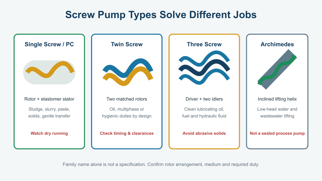
The family name is not a specification: confirm rotor arrangement, medium and duty before comparing quotations.
This design is the main focus of Shinjo's current screw-pump collection. It is useful for sludge, slurry, pulp, food paste, adhesive, polymer, oil-water mixture and other viscous or solids-bearing media when materials and speed are selected correctly.
Choose it when the process values low-pulsation metering, gentle handling, suction capability or solids passage. Question it when dry running is frequent, the fluid attacks available stators, large hard solids exceed cavity dimensions, or maintenance access is too restricted for rotor-stator replacement.
Twin-screw pumps use two intermeshing screws to move fluid axially. Some designs use external timing gears so the rotors do not touch, allowing them to handle non-lubricating media unlike some other pump technologies. Depending on design, they can serve crude oil, multiphase mixtures, terminals, hygienic food processes or clean-in-place systems.
They can offer high capacity and broad viscosity handling, but they require more precise rotor geometry, timing and clearances. Do not assume a twin-screw pump tolerates any solids or can run dry simply because the rotors do not contact each other. Seal, bearing, timing-gear and casing limits still apply.
Shinjo's reviewed collection does not currently provide evidence of a twin-screw product. This type is explained for comparison, not presented as a Shinjo offering.
A triple screw pump, and triple screw pumps more broadly, usually has one screw driven while two idler screws follow. It produces smooth flow and can reach substantial pressure with clean, lubricating liquids such as fuel oil, lube oil and hydraulic oil, so these units are common in hydraulic systems and lubrication systems.
Its tight clearances make dirty or abrasive service risky, and they also make a triple screw unsuitable for many abrasive materials or soft solids despite its pressure capability. Low-lubricity liquids may not support the intended hydrodynamic film. It is therefore not the default replacement for a progressive-cavity sludge pump even though both are called screw pumps.
An Archimedes screw uses a large rotating helix to lift water, sewage or solids through an inclined trough. It is valuable for high flow at low head and can pass debris with low rotational speed. It does not use a sealed elastomer stator, does not behave like an enclosed high-pressure process pump and is normally a civil/water-infrastructure installation.
The term appears in broad search results, so the distinction should be explicit. A buyer moving syrup through a closed sanitary line and a municipality lifting wastewater through an open channel are not selecting the same technology.
A dry screw vacuum pump moves and compresses gas between non-contacting rotors. Vacuum level, pumping speed, gas composition, cooling and condensate tolerance govern selection. Those data should not be copied into a liquid screw-pump sizing calculation. Treat vacuum pumps as a separate topic.
This comparison is partly a naming issue. A progressive-cavity pump is commonly considered a single-screw positive-displacement pump because one helical rotor moves inside a stator. "Screw pump" is the broader family name and may also refer to twin-screw, three-screw, Archimedes or vacuum designs.
If a specification says only "screw pump," ask:
- Is the required mechanism a progressive-cavity rotor and elastomer stator?
- Does the liquid contain solids, fibres or abrasive particles?
- Must the pump handle clean lubricating oil, multiphase fluid or hygienic CIP duty?
- Is the service liquid transfer, open-channel lifting or gas vacuum?
The answer determines the family before size or price is discussed.
| Decision factor | Progressive-cavity screw pump | Centrifugal pump | Gear pump |
|---|---|---|---|
| Flow behaviour | Approximate displacement proportional to speed, with slip | Depends strongly on system curve and impeller curve | Approximate displacement proportional to speed, with slip |
| High viscosity | Usually strong when speed and inlet are suitable | Capacity and efficiency may deteriorate significantly | Strong for compatible clean viscous liquids |
| Suspended solids/fibres | Can be strong within particle/fibre limits | Depends on impeller and passage design | Usually poor for hard solids due to close clearances |
| Shear | Often relatively gentle | Can be higher at impeller and high speed | Can shear product through close clearances |
| Pulsation | Low when fed and selected correctly | Smooth | Low to moderate depending on gear geometry |
| Dry running | Often damaging to stator | Model-dependent; generally undesirable | Model- and liquid-dependent |
| Dead-heading | Dangerous without protection | May be tolerated briefly by some designs but causes heating | Dangerous without protection |
| Main wear concern | Rotor, stator, joints and seal | Impeller, casing/wear rings, bearings and seal | Gears, bushings, casing and seal |
Choose a centrifugal pump for many clean, low- to moderate-viscosity, high-flow services where the operating point can be matched to a pump curve. Different pump technologies suit different fluid types. Choose a progressive-cavity pump when viscosity, solids, gentle handling, suction or metering makes centrifugal performance unsuitable. Choose a gear pump for clean lubricating fluids and compact metering/transfer duties where solids are controlled, though screw pumps often suit higher-viscosity fluid types requiring gentler, more continuous transfer than many other pump technologies.
The comparison must be made at the actual fluid temperature. A product that pours easily at 80°C may become too viscous for the selected pump and motor during a cold start.
An industry name does not provide enough information. Two wastewater plants may handle completely different sludge concentrations, and two food factories may have different particle, temperature and cleaning requirements.
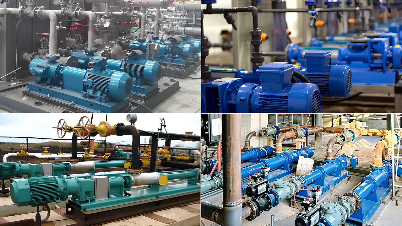
Illustrative application scenes. Actual suitability depends on viscosity, solids, temperature, chemical compatibility, hygiene requirements and the selected pump construction.
Progressive-cavity pumps are widely used in wastewater treatment for primary sludge, dewatered sludge feed, polymer dosing, and related solids-bearing streams. The buyer should define dry-solids percentage, particle size, fibre length, abrasiveness and whether gas is entrained. A wide hopper or feed screw may be necessary for material that will not flow into a standard suction port.
For highly abrasive mineral solids, compare the expected wear cost with a purpose-designed slurry pump. The fact that a progressive-cavity pump can pass solids does not mean it is always the lowest-cost abrasive-duty option.
Syrup, honey, fruit pulp, sauces, cream and dough-like materials benefit from gentle transport and controlled flow. Hygienic service adds requirements for approved wetted materials, surface finish, drainability, cleanability, dead-leg control and food-compatible elastomers. A stainless casing alone does not make the complete pump hygienic.
Adhesives, resins, latex, emulsions, coatings and chemical slurry require exact compatibility review. Provide a safety data sheet, concentration and cleaning chemical list. For clean aggressive chemicals without solids, compare a chemical process pump or magnetic-drive option before defaulting to an elastomer-stator pump.
Progressive-cavity pumps can move crude oil, oily sludge and oil-water mixtures. Twin- or three-screw technology may suit other petroleum duties in the gas industry. Gas fraction, sand, temperature, viscosity range for high viscosity fluids, vapour pressure and hazardous-area classification become central. "Oil pump" is not a complete specification.
Mortar, lime slurry, plaster and coatings can be moved or sprayed with progressive-cavity technology. Particle grading and maximum aggregate size must fit the pump and hose. Never infer capability from viscosity alone; a hard particle can jam or cut a stator even when the paste flows easily.
Pulp, coating colour, starch and chemical additives may benefit from low pulsation and speed control. Long fibres can bridge at the inlet, so fibre length and orientation matter. Dosing accuracy should be validated over the required pressure and speed range rather than assumed from theoretical displacement.
- Handles viscosity: positive displacement preserves useful flow better than many centrifugal designs when handling high viscosity fluids as viscosity rises, provided the inlet can fill the cavities.
- Low pulsation: continuous rotor movement supports continuous flow with low pulsation for dosing and process stability when the pump is fed correctly.
- Solids and fibres: progressive cavities can transport suspended material within model-specific dimensional and concentration limits.
- Gentle handling: low internal velocity can reduce product damage for some shear-sensitive media.
- Speed-based control: VFD operation can vary output without wasting pressure across a throttling valve.
- Suction capability: many designs can self-prime and work with difficult suction duties when piping and speed are engineered correctly, but that performance and service life depend on staying within approved speed, material, and protection limits.
- The elastomer stator can be damaged by dry running, heat, chemical incompatibility or abrasive wear.
- Flow can fall as rotor-stator sealing lines wear and slip increases.
- High-viscosity or poorly fed material may require a larger inlet, hopper or force-feeding arrangement.
- Positive displacement requires reliable discharge overpressure protection.
- Replacement of long rotor-stator assemblies needs maintenance space.
- Product and cleaning-fluid compatibility may require compromises between chemical resistance, abrasion and temperature.
- Purchase price alone does not show stator, rotor, seal and downtime cost.
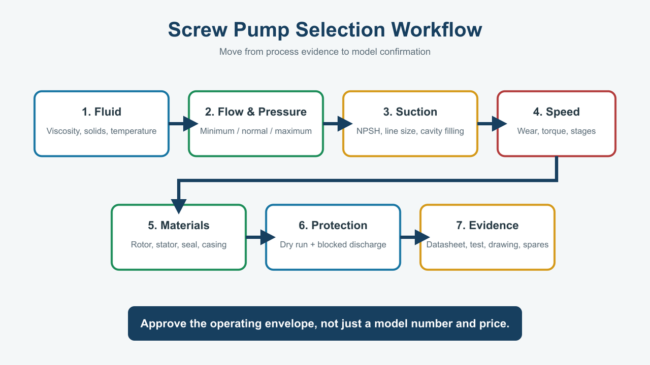
A defensible selection starts with process evidence and ends with an approved operating envelope, datasheet, drawing, test plan and spare-parts scope.
Record the fluid types, composition, concentration, pH, density and vapour behaviour. State minimum, normal and maximum viscosity with the corresponding temperatures. For non-Newtonian material, include available rheology or test data because one viscosity number may not describe startup and shearing behaviour.
List solids concentration, maximum particle dimensions, soft solids, hardness, shape and fibre length. State whether the product settles, crystallises, cures, foams or separates while stopped.
Why it matters: this information controls pump family, stator compound, rotor coating, speed, seal, inlet and cleaning plan.
Specify continuous and intermittent demand in consistent units. Do not provide only peak capacity. Minimum flow helps the manufacturer check the lower speed range, motor cooling, controllability and whether a smaller pump would operate more efficiently.
Success check: the proposed speed range should cover normal operation without living at the extreme minimum or maximum rating.
Include downstream static pressure, elevation, pipe and fitting losses, equipment pressure drop and any variable backpressure. Suction pressure may be positive or negative and affects the net differential across the pump. Shinjo's pump head loss guide and total head explanation help organise the system terms, but the final calculation must reflect the actual fluid and line.
Warning: do not use only vertical lift. Viscous friction can dominate a long pipe.
Provide tank level range, suction pipe diameter and length, fittings, available pressure, fluid temperature and vapour pressure. Evaluate NPSHA against manufacturer requirements and consider viscous inlet loss separately. Keep suction piping short and generously sized where possible.
Stop condition: if the selected speed prevents complete cavity filling, a larger/slower pump or force-feed arrangement is needed. Do not solve starvation by increasing speed.
Lower speed generally reduces wear and improves cavity filling for abrasive or viscous material, although the exact trade-off is model-specific. Pressure stages must cover differential pressure with suitable margin. Confirm maximum allowable pressure per stage and total pump rating from the manufacturer.
Success check: normal duty should sit inside the approved speed-pressure-viscosity envelope, not merely below a catalogue maximum.
Review casing, rotor, coating, stator, joint protection, seal faces, secondary seals and gaskets. Check both process fluid and cleaning chemicals at temperature. Request a written material schedule rather than accepting "stainless steel pump."
Warning: a compatible casing cannot compensate for an incompatible elastomer stator.
Consider maximum differential pressure, cold viscosity, starting condition, stator interference and mechanical losses. Specify motor voltage, frequency, enclosure, efficiency, hazardous area, service factor and VFD range.
Success check: obtain gearbox output torque and motor power calculations or manufacturer selection confirmation, not just a motor kW value copied from a nearby model.
Provide discharge relief, pressure monitoring, dry-run protection, low-level shutdown and any seal-flush or temperature monitoring required. Interlock downstream valves where a closed valve can dead-head the pump.
Stop condition: do not commission a positive-displacement pump into an isolatable discharge without an approved overpressure path.
Confirm how the pump will be drained, flushed and dismantled. Reserve axial space to remove the rotor and stator. Ask for recommended spares for two years or the project's chosen maintenance period, including stator, rotor inspection criteria, seal kit, joint parts and gaskets, and note that planned inspection and correct operating limits help extend service life.
A buyer orders a stainless progressive-cavity pump for adhesive and assumes stainless wetted parts solve compatibility. The solvent swells the stator, startup current rises and the drive trips. The missing decision was elastomer compatibility, not casing material.
Prevention: supply the adhesive composition, concentration, temperature and cleaning solvent; request written confirmation for the stator and secondary seals.
A pump is selected from peak flow alone and runs near maximum speed. Abrasive particles and other abrasive materials repeatedly cross the sealing lines, rotor coating wears and capacity falls. Operators increase speed to recover flow, accelerating the wear cycle.
Prevention: compare a larger slower pump, confirm solids data and calculate lifecycle cost against alternative slurry-pump technology; for some duties with leading manufacturers' purpose-designed slurry alternatives, that option may be better if lifecycle cost is lower.
A downstream valve closes while the screw pump continues displacing liquid. Pressure rises until a seal, hose, flange or drive component fails.
Prevention: engineer a relief path and shutdown logic for the credible blocked-discharge case. Training is useful but is not a substitute for hardware protection.
| Symptom | Likely causes | First checks |
|---|---|---|
| Low or falling flow | Worn rotor/stator, slip, low speed, blocked inlet, starvation, gas | Confirm speed and pressure, inspect suction, compare actual flow with baseline |
| High motor current | High viscosity, excess pressure, stator swelling, obstruction, joint damage | Check temperature, discharge pressure, rotation and free mechanical movement |
| Stator overheating | Dry running, poor lubrication, excessive interference, high speed | Stop pump, verify inlet supply and inspect stator before restart |
| Failure to prime | Air leak, excessive lift, empty/blocked suction, worn sealing lines | Leak-test suction, confirm liquid level and model priming limit |
| Vibration or noise | Starved inlet, solids jam, worn joints, misalignment, unstable foundation | Inspect feed, joints, alignment and supports |
| Seal leakage | Worn faces, incompatible elastomer, dry seal, pressure upset | Identify leak location and review seal plan/materials |
| Rapid rotor/stator wear | Abrasion, speed, incompatible material, insufficient stages | Review solids, coating, stator compound and pressure per stage |
Troubleshooting should begin with recorded evidence: inlet condition, discharge pressure, speed, current, temperature, flow and fluid state. Replacing the stator without finding starvation or chemical attack often repeats the failure.
Establish a baseline after commissioning. Record flow, pressure, speed, motor current and vibration at normal duty. Trend change over time, and use that data with preventive maintenance practices to improve service life. A progressive decline in flow at the same speed and pressure suggests growing slip; a sudden current increase suggests a different problem such as obstruction, viscosity change or stator swelling.
Shinjo currently lists five products in its screw-pump category. The linked model pages describe progressive-cavity single-screw construction rather than one common Archimedes-style water screw. Buyers should use the category for navigation and the exact model page and current datasheet for selection.
The G Type single screw pump page publishes a 0.8-150 m3/h overall flow range, DN25-DN250 connections and motor power from 0.75 to 90 kW. Its model tables include pressure stages, speed, power, NPSH and stated particle/fibre dimensions. This provides a useful starting point for wastewater, food, chemical, construction and pulp duties, but the supplier must still select the model from actual viscosity, solids, pressure and materials.
The I-1B single screw pump page publishes 1.5-35 m3/h flow, 50-120 m head, DN25-DN150 size, 1.5-15 kW motor power and 960 rpm. It is positioned for slurry, suspension and viscous media across food, metallurgy, construction, pharmaceutical and chemical sectors. Those application labels do not replace a solids and compatibility review.
The GNF stainless steel single screw pump page publishes 1.5-20 m3/h flow, DN32/DN50/DN100 options and 1.5-11 kW motor power. It describes stainless/acid-resistant wetted metal parts, a rubber stator and applications involving food slurry, chemical, petroleum and sewage processes. Ask for the exact stainless grade, stator compound, allowable temperature and sanitary documentation required by the project.
Manufacturer evidence note: Do not combine the largest number from every Shinjo model into a fictitious master specification. Request the current model datasheet, curve or performance table, dimensional drawing, materials list, motor/gearbox data and test scope for the selected duty.
Screw pump price depends on displacement, pressure stages, stator compound, rotor material/coating, casing, seal, gearbox, motor, VFD, baseplate, instruments, testing and documentation. A low quote can be expensive if the stator fails in the process chemical or the pump operates too fast and consumes wear parts.
Send the following data with the RFQ:
| RFQ item | Buyer input required | Why the supplier needs it |
|---|---|---|
| Medium | Exact name and composition | Establish pump family and materials |
| Viscosity | Min/normal/max with temperature | Check filling, speed, slip and torque |
| Solids | Concentration, maximum size, hardness and fibre length | Check passage, abrasion and inlet design |
| Flow | Minimum, normal and maximum | Select displacement and speed range |
| Suction | Tank level, pressure, line and temperature | Confirm filling and NPSH margin |
| Discharge | Pressure plus pipe/equipment losses | Select pressure stages and drive |
| Materials | Casing, rotor, stator and seal requirements | Prevent corrosion, swelling and contamination |
| Duty cycle | Continuous/intermittent, starts per hour | Check thermal and mechanical loading |
| Motor | Voltage, frequency, enclosure and area class | Supply a compliant drive package |
| Controls | VFD, dry-run and pressure protection | Define operating and safety architecture |
| Cleaning | Flush/CIP chemicals, temperature and frequency | Confirm compatibility and drainability |
| Documents | Test report, certificates, drawing, manual and spares | Support approval, installation and maintenance |
Buyer note: A useful quotation should state the selected model, speed range, differential pressure, materials, motor/gearbox, assumptions and protection requirements. Quotations from leading manufacturers should also define the support scope, not just the model number and price. A model number and price without the sizing basis do not show whether the pump will survive the application.
Industrial single-, twin- and three-screw liquid pumps are positive-displacement machines. They move trapped volumes rather than relying on an impeller dynamic head. An Archimedes screw is normally treated as a low-head lifting device and should be discussed separately.
A progressive-cavity pump is commonly classified as a single-screw pump. "Screw pump" is broader and can also describe twin- and three-screw designs, so the specification should name the actual mechanism.
Do not assume so. Progressive-cavity pumps commonly depend on liquid for rotor-stator lubrication and cooling, and dry running can damage the stator quickly. Follow the exact model limit and install suitable protection.
Many progressive-cavity and other screw pumps have self-priming capability under specified conditions. Actual lift depends on speed, sealing condition, viscosity, suction piping and model design. Self-priming does not permit indefinite dry operation.
A progressive-cavity pump can handle solids and fibres within model-specific limits. State particle size, concentration, hardness, shape and fibre length. Large, sharp or abrasive solids can block or wear the pump.
Flow is commonly adjusted by changing rotational speed with a VFD, which changes flow rate, though the usable range depends on viscosity, pressure, and cavity filling. The manufacturer should confirm the allowable speed range, motor cooling, and cavity-filling limits.
Pressure can rise rapidly because the pump continues displacing volume. Provide engineered relief and shutdown protection; do not rely on an operator opening the valve in time.
Choose a centrifugal pump for many clean, lower-viscosity, high-flow duties where a suitable pump curve matches the system. Compare that choice against other pump technologies using the actual fluid type, viscosity, solids content, and required pressure. Choose a progressive-cavity pump when viscosity, solids, gentle handling, suction or controlled positive displacement justifies its added wear-part considerations.
Start with the fluid and duty, not the existing pipe size and not the word "screw." First identify whether the application needs a progressive-cavity, twin-screw, three-screw, Archimedes or vacuum mechanism. Then confirm viscosity at temperature, solids, minimum and maximum flow, differential pressure, suction condition, materials, speed, torque and protection.
For Shinjo's current progressive-cavity range, use the G, I-1B and GNF model data as a starting point and request project-specific confirmation. The best selection is not the pump with the largest catalogue range. It is the pump that fills correctly, operates at a sustainable speed, uses compatible rotor-stator materials, has safe discharge protection and can be maintained with available spares.
