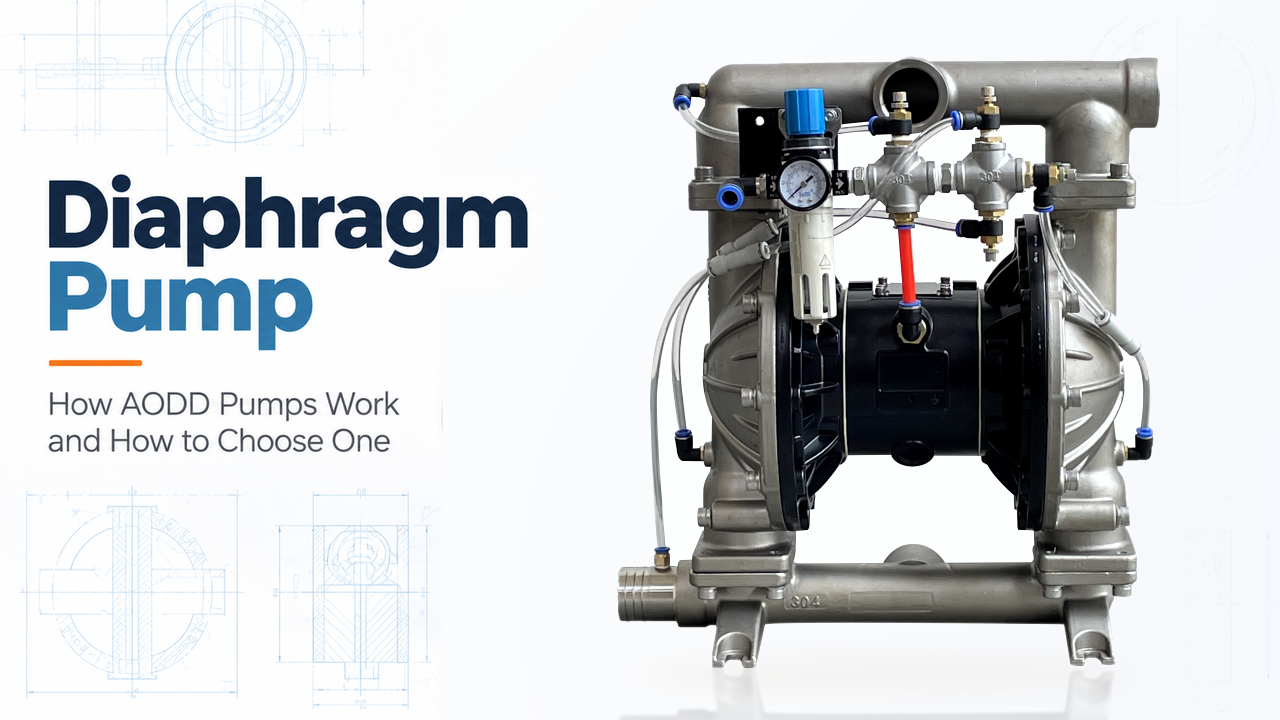
A diaphragm pump moves liquid or gas by flexing a membrane rather than using an impeller or a packed piston. That simple idea has an important consequence: the diaphragm separates the process medium from the drive side. For industrial liquid transfer, this can make a diaphragm pump a practical option for corrosive liquids, coatings, liquids containing solids, viscous products, intermittent transfer and duties where a conventional rotating seal would create a difficult maintenance question.
The name, however, covers several different technologies. A laboratory diaphragm vacuum pump, a metering diaphragm pump and an air-operated double diaphragm pump do not solve the same job. This guide focuses on the industrial liquid-transfer family most relevant to Shinjo Pump: air-operated double diaphragm pumps, often called AODD pumps, plus the separate motor-driven diaphragm option in its published range. Start with the available diaphragm pumps, then use the process data in this guide to decide which construction deserves a detailed quotation.
A diaphragm pump is a positive-displacement pump. Instead of continuously adding velocity to liquid like a centrifugal pump, it repeatedly enlarges and reduces a pumping chamber. During the enlarging part of the cycle, the chamber draws liquid in. During the reducing part, it pushes liquid out. Check valves, balls, flaps or similar components keep the liquid moving in the intended direction.
In an air-operated double diaphragm pump, two diaphragms are connected by a common shaft. Compressed air is directed alternately behind each diaphragm. One liquid chamber discharges while the opposite chamber fills, then the air valve reverses the action. This alternating motion is the reason AODD pumps can transfer difficult fluids, but it is also why their delivered flow is pulsating and must be assessed as part of a complete system.
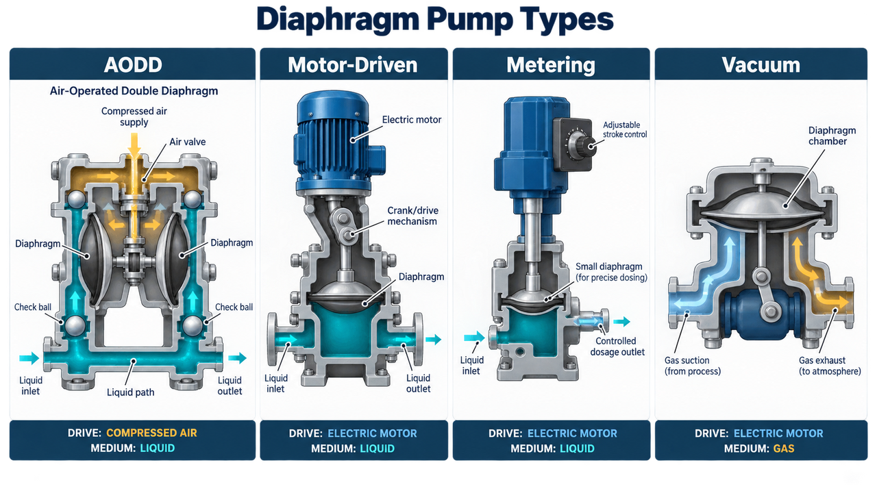
The word "diaphragm" describes the flexible barrier that creates or changes a chamber. The family name alone cannot identify one universal pump. Drive method, chamber arrangement and the job being performed change the pump's performance, controls, maintenance needs and the information required for a quotation. A buyer should choose the family before comparing port size, pump body material or price.
Pump family | Basic construction | Main medium and duty | Choose it when | Do not confuse it with |
Air-operated double diaphragm pump (AODD) | Two diaphragms joined by a shaft; an air valve alternates compressed air between the rear chambers | Industrial liquid transfer | Intermittent transfer, difficult liquids, portable duty or a site where compressed air is already a suitable utility | A metering pump or a vacuum pump |
Motor-driven diaphragm pump | Electric motor and mechanical drive move one or more diaphragms | Industrial liquid transfer | Electric power is preferred and the proposed model's flow, head and materials suit the duty | An AODD with an electric motor added afterward |
Metering diaphragm pump | A controlled mechanical, hydraulic or solenoid drive displaces small repeatable volumes | Chemical dosing and controlled injection | The process needs a defined dosage rate and a verified accuracy range | A general transfer pump |
Diaphragm vacuum pump | A diaphragm changes a gas chamber volume, often in one or more stages | Gas evacuation and rough-vacuum generation | The job is removing gas or creating vacuum, not moving bulk liquid through a process line | A liquid-transfer diaphragm pump |
The four families can share words such as diaphragm, chamber, suction and discharge, yet they are selected around different performance measures. AODD selection turns on air supply, wet-end materials, check elements, suction conditions and pulsation. A metering pump has a dosing-rate and accuracy question. A vacuum pump is evaluated around gas load and vacuum performance. Mixing those measurement systems is how a plausible-looking pump becomes the wrong purchase.
An AODD pump has two liquid chambers separated from two air chambers by flexible diaphragms. A compressed-air distribution valve sends air behind one diaphragm while allowing air to exhaust from the other side. Because the diaphragms are tied together, one liquid chamber is in its discharge stroke while the other is in its suction stroke. Check balls, flaps or other one-way elements open and close from pressure difference, directing liquid from inlet manifold to chamber and then from chamber to outlet manifold.
This design is often considered for chemicals, coatings, adhesives, waste liquids, slurries and tote or drum transfer because the liquid path can be configured with different body, diaphragm, seat and check-element materials. Frequent start-stop transfer, use of an existing compressed-air utility and portable duty are further reasons to consider it. The real advantage is not that an AODD pump handles every difficult medium. The drive side and wet end can be reviewed separately, then matched to the medium and the site.
Within the AODD family, three choices still change the duty substantially:
Wet-end construction: Shinjo Pump's published category includes aluminium alloy, cast iron, stainless steel, fluoroplastic, PP, PVDF, PTFE and PFA directions. Those names narrow the discussion; they do not replace compatibility review of every wetted component.
Check-element arrangement: A ball and seat arrangement may react differently to a sticky, fibrous or settling product than a flap-style arrangement. The expected solids, particle shape and cleanout method should be in the application data.
Connection and installation configuration: A threaded portable-transfer unit, a flanged process pump and a model with a different manifold orientation can share an AODD mechanism but create very different piping and maintenance constraints.
Shinjo Pump's DN80 air-operated diaphragm pump and NPT stainless steel diaphragm pump illustrate this point: published pages show different body, diaphragm and connection directions even where the nominal size is similar. Confirm the complete proposed configuration rather than selecting from "AODD" alone.
A motor-driven diaphragm pump replaces the pneumatic air-distribution system with an electric motor and mechanical drive. The drive converts rotary motion into repeated diaphragm movement. It remains a positive-displacement liquid-transfer machine, but its controls, utilities and installation questions are different. Motor data, voltage, enclosure, gearbox or drive arrangement, speed range and power availability now belong in the selection review; compressed-air volume, exhaust routing and icing do not carry the same weight.
This family can make sense where plant air is limited, costly or unavailable, or where the operating team needs an electrically driven package. No automatic gain in smoothness, accuracy or lifecycle cost follows from choosing a motor-driven design. The answer depends on the actual liquid duty, expected operating pattern and the specific construction. Pulsation, compatible diaphragms and check elements, and a safe response to a blocked discharge remain part of the engineering review.
Shinjo Pump publishes a DBY motor-driven diaphragm pump with a stated 0.5-16 m3/h flow range, up to 70 m head and a 3-7 m published suction-head range. Those values identify the product direction, not a universal site result. The exact flow, motor arrangement, medium, back pressure, material set and suction conditions still need to appear in the quotation.
Metering diaphragm pumps are built for a different promise: controlled dosing of a specified liquid quantity over time. A diaphragm separates the drive mechanism from the liquid, but the defining feature is the controlled displacement and the ability to adjust or verify dosage. Depending on design, the pump may use a mechanical, hydraulic or solenoid drive. Its selection involves dose rate, turndown, system pressure, stroke setting, injection point, calibration method, liquid properties and the required accuracy under real operating conditions.
A transfer pump should not be promoted as a metering pump merely because it can move a small flow. AODD output changes with air pressure, back pressure, viscosity, cycle rate and suction conditions. Those characteristics can be acceptable for transfer, but they do not prove dosing accuracy. Conversely, a metering pump can be an excellent choice for chemical injection while being a poor fit for a bulk transfer task involving high solids or rapid drum emptying.
Shinjo Pump's reviewed diaphragm-pump collection is presented here as an AODD and motor-driven liquid-transfer range. This metering category is included to prevent a buyer from applying a dosing requirement to the wrong family; it is not presented as a documented Shinjo Pump offering.
Diaphragm vacuum pumps work on gas, not process liquid. The diaphragm moves to increase and decrease the volume of a gas chamber. During the expanding stroke, gas enters at the suction side; during compression, it leaves through the outlet path. Multi-stage configurations, dead space, gas composition, vapor load, ultimate vacuum and pumping speed are central to vacuum selection.
Leybold's explanation of diaphragm vacuum pumps discusses dry compression, dead space and ultimate vacuum in that correct vacuum context. Those concepts are valuable for laboratory and industrial vacuum systems, but they cannot be carried into a liquid-transfer AODD calculation. A plant that needs to evacuate gas from a vessel is solving a different problem from one that needs to transfer corrosive liquid from a tote. Leybold's vacuum-pump explanation should therefore be read as a separate technical path.
Start with the medium and the outcome. Select AODD when the job is industrial liquid transfer and the air supply, pulsation and wet-end materials can be made to work together. Consider a motor-driven diaphragm pump when electric drive is more appropriate and its model-specific performance covers the duty. Specify a metering pump when the value of the system lies in a controlled dose rather than bulk transfer. Select a vacuum pump only when the medium is gas and vacuum performance is the governing question.
Choosing the type first avoids a common RFQ failure: suppliers quote different machines under the same broad name and every price looks comparable until commissioning. A credible inquiry names the required pump family, then supplies the liquid or gas data, flow range, pressure condition, temperature, utilities and materials needed to select a real model.
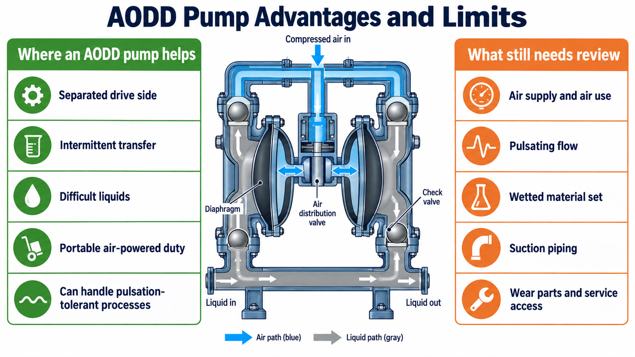
An AODD pump earns its place when its mechanism solves a real process problem. The separated drive side can reduce the reliance on a conventional rotating shaft seal in the liquid path. Its positive-displacement strokes can be useful for intermittent transfer and liquids that do not behave like clean water. Available plant air or a portable-transfer requirement may also favor pneumatic drive. Those are advantages, but none of them is a blanket guarantee of chemical compatibility, dry-running duration, flow stability or low lifecycle cost.
Potential advantage | Why it can help | Where the advantage stops |
Separated drive side | The liquid chamber is separated from the air-side drive mechanism | Every wetted component, especially the diaphragms, seats and check elements, must still suit the medium and cleaning liquid |
Positive-displacement transfer | Can suit intermittent transfer, viscous products and selected solids-bearing liquids | Actual delivery changes with suction conditions, back pressure, viscosity and check-valve behavior |
Air-operated drive | Useful where compressed air is available and a pneumatic package suits the site | Air pressure and volume at the pump, air quality, exhaust routing, noise and icing still need review |
Self-priming capability in suitable duties | May simplify transfer from drums, totes or a lower liquid source | A long, restrictive or leaking suction line can still prevent reliable filling of the chambers |
Deadhead-capable operation in some designs | Some models can stop cycling when discharge resistance reaches the available driving condition | This must be confirmed for the exact model and does not replace a review of trapped pressure, hose rating or isolation philosophy |
Serviceable wear components | Diaphragms, seats and check elements can support a planned spares strategy | The real cost depends on cycle duty, abrasion, chemical exposure and whether the installation allows safe service access |
The limitation that most often surprises a first-time buyer is that a diaphragm pump is a system, not a stand-alone answer. A favorable pump body material cannot compensate for an incompatible diaphragm. A large port does not guarantee the required flow. A suitable air-operated pump still fails to meet duty when the compressor, air line or suction arrangement is undersized. That is why the selection sections below ask for a curve, a complete wetted-material declaration and site data rather than a product name alone.
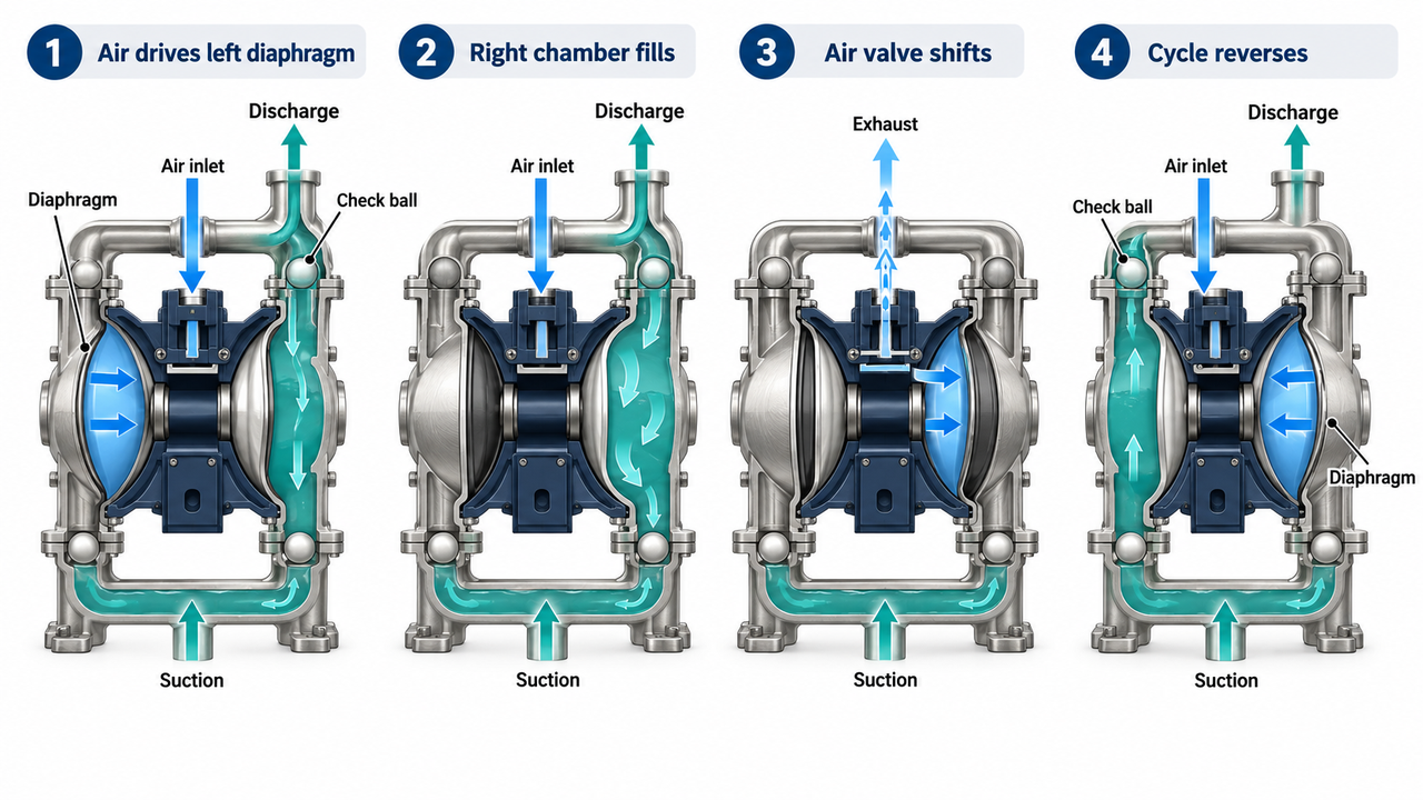
An AODD pump has two linked circuits that must be read together. The compressed-air circuit does the work of moving the diaphragms. The liquid circuit uses the changing volume of each liquid chamber and one-way check elements to draw liquid in and push it out. The liquid never needs to pass through the air valve; the diaphragm is the barrier between the two sides.
The paired diaphragms are mechanically connected by a shaft. When the air valve sends compressed air to the rear of the left diaphragm, that diaphragm moves outward and reduces the volume of its liquid chamber. The shaft moves the right diaphragm in the opposite direction, enlarging its liquid chamber. The left chamber is therefore discharging while the right chamber is filling. At the end of the stroke, the air valve changes over and the two sides trade jobs. This is why the pump produces transfer on both halves of the cycle, but still produces a pulsating outlet rather than perfectly continuous flow.
Stage | Air circuit | Liquid circuit | Process consequence |
1. Left discharge stroke | Compressed air enters the left air chamber and pushes its diaphragm toward the liquid chamber | Pressure rises in the left liquid chamber; its inlet check closes and its outlet check opens | The pump must overcome downstream pressure, pipe losses and liquid resistance before discharge begins |
2. Right suction stroke | Air on the right side is directed to exhaust while the common shaft pulls the right diaphragm away from its liquid chamber | Chamber volume increases; its outlet check closes and inlet check opens if suction conditions allow liquid to enter | A restrictive, leaking or air-bound suction line prevents the chamber from filling fully |
3. End-of-stroke reversal | The air-distribution mechanism senses or is actuated at the end of travel and switches the air path | The left discharge chamber reaches the end of its stroke; the right chamber has filled as far as the inlet allows | Dirty or wet air, a sticking air valve or restricted exhaust can delay or interrupt cycling |
4. Right discharge stroke | Compressed air now acts on the right diaphragm while the left side exhausts | The right chamber discharges and the left chamber refills | The repeated exchange creates the pump's characteristic pulse frequency and flow pattern |
The mechanism explains several field observations that otherwise look unrelated. A pump can cycle quickly but move little liquid when the inlet chamber is not filling. Rising back pressure slows the discharge stroke because the chamber faces more resistance. Colder, more viscous liquid may reduce apparent capacity because it is harder to pull through the suction line and the check elements respond differently. The unit may even sound normal while producing unacceptable pressure variation at a sensitive downstream meter or filling nozzle.
Check elements are essential to that sequence. A check ball lifts from its seat only when the pressure difference is in the correct direction. During suction, low pressure in the expanding chamber encourages the inlet check to open while the outlet check stays closed. During discharge, increased chamber pressure closes the inlet check and opens the outlet check. If a ball is held off its seat by a fiber, crystallized deposit, sticky coating or damaged seat, some of the displaced liquid can return in the wrong direction. The operator sees reduced flow or erratic cycling, yet the diaphragm itself may not be damaged.
The air valve is equally important. Its role is to alternate the air supply so the diaphragms can cycle; it does not establish a fixed liquid flow. The delivered rate still depends on air pressure and volume at the pump, back pressure, liquid viscosity, suction fill, check-element behavior and the actual piping system. That is why a compressor's rated capacity and a pump's maximum-flow figure cannot be joined together as a selection calculation without a curve or an application review.
The sequence above describes the operating logic behind Shinjo Pump's published air-operated double diaphragm models. The product pages also show why "diaphragm pump" is not enough specification. The published DN80 air-operated diaphragm pump is listed with DN80 / 3-inch connections, an aluminium-alloy housing, PTFE diaphragms, 53 m3/h stated flow and 84 m stated head. The published NPT stainless steel model is listed with DN80 / 3-inch NPT ends, 304 stainless steel housing, FEP diaphragms, and the same stated flow and head.
Those figures are manufacturer-published model information, not a prediction for every fluid or installation. A short flooded line carrying a low-viscosity liquid will not load the pump in the same way as a long suction hose moving a cold coating. In an RFQ, state the liquid condition and ask the supplier to identify the curve, air requirement, materials and test basis that support the proposed point.
Published Shinjo Pump configuration | What the listing establishes | Why it matters | What remains project-specific |
Pneumatic drive; DN80 / 3-inch; aluminium-alloy body; PTFE diaphragms; stated 53 m3/h flow and 84 m head | Air drive, body and diaphragm are selected as one configuration | Air pressure and volume at the pump, medium viscosity, back pressure, suction conditions, check-element materials and performance basis | |
DN80 / 3-inch NPT; 304 stainless steel body; FEP diaphragms; stated 53 m3/h flow and 84 m head | Connection and wet-end direction can change even at a similar nominal size | Chemical concentration, temperature, all wetted parts, connection standard, cleaning medium and required documents | |
Electric motor drive; stated 0.5-16 m3/h flow, up to 70 m head and 3-7 m suction head | Motor-driven diaphragm duty must be judged as a separate configuration | Motor, power supply, actual duty, materials, solids limit and installation arrangement |
Published-data note: Shinjo Pump's category page gives a general overview while individual product cards show different capacities and heads. Use the exact model page, current data sheet and confirmed operating conditions for a quotation. Do not combine the largest number from different listings into a fictional all-series rating.
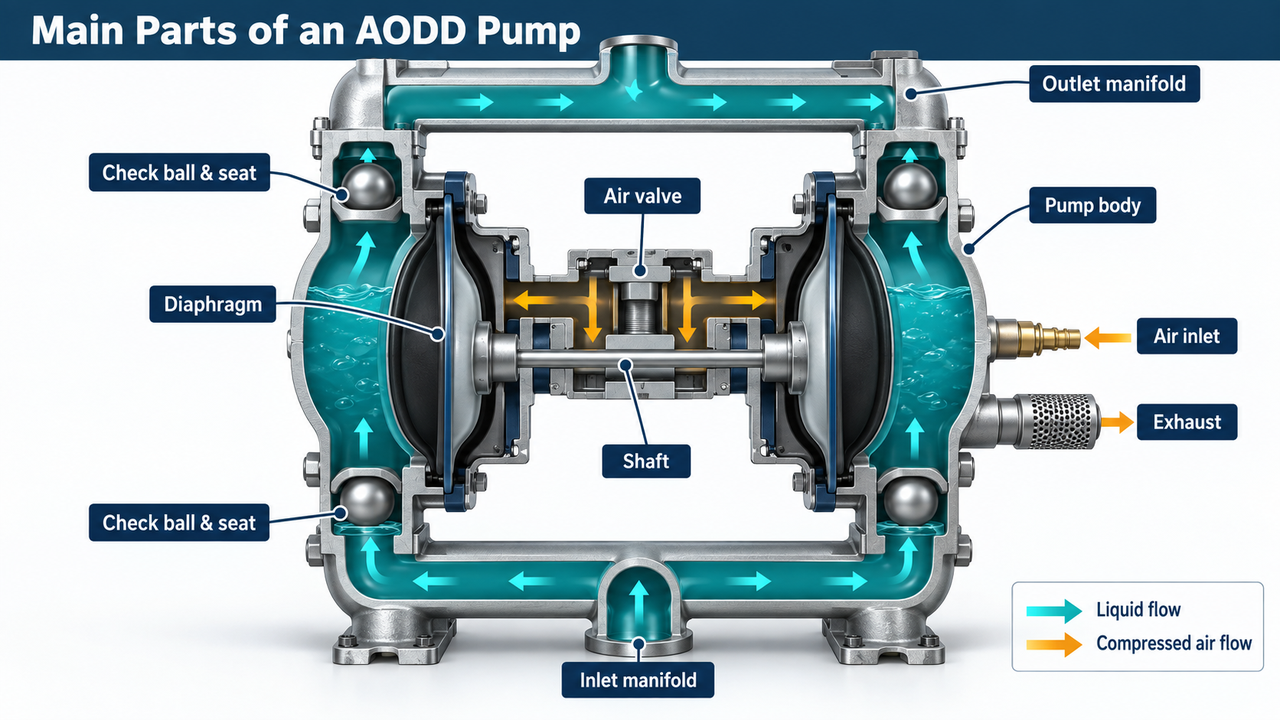
Every main part changes either containment, flow direction, air cycling, wear life or maintainability. The useful way to inspect an AODD pump is not to memorize names, but to ask what each component does to the process and what failure it is exposed to.
The diaphragms flex on every stroke. They form the moving wall of each liquid chamber and isolate the liquid from the air drive side. Their material must handle the process liquid, temperature, cleaning medium and expected flexing duty. Chemical incompatibility may appear as swelling, hardening, cracking or loss of strength. High temperature, excessive cycle rate and abrasive or entrained material can also change service life.
For that reason, "PTFE diaphragm" or "FEP diaphragm" is not a complete approval statement. The buyer needs the whole material combination, the actual temperature range and the supplier's confirmation for the specific liquid. A compatible body cannot rescue an incompatible diaphragm because the diaphragm is one of the primary containment barriers.
The air valve sends compressed air alternately to the two rear chambers and provides the exhaust path from the side that is retracting. Its cycling behavior determines the diaphragm sequence. Air contamination, water, inadequate pressure at the pump, a restricted exhaust or a sticking valve can all appear as slow, irregular or stopped operation.
Treat the air supply as part of the pump. Record pressure at the pump while it is running, not only compressor pressure elsewhere in the plant. Confirm the line size, regulator, air quality requirement, drainage and exhaust location. In cold or humid service, rapid expansion at the exhaust can create a cooling or icing concern that should be addressed during design rather than after cycling becomes unstable.
The shaft ties the two diaphragms together so one side fills as the other side discharges. Diaphragm plates or retaining hardware transmit that movement to the flexible diaphragms. These are mechanical drive components, but they also affect containment because assembly condition influences diaphragm support and sealing. During service, use the correct manufacturer's procedure, fastening sequence and torque values. A generic repair practice can damage a new diaphragm or leave an assembly that leaks under cycling.
The check elements are the pump's traffic control. Their job is to let liquid enter each chamber during suction and leave it during discharge, without allowing reverse flow. Ball, flap and seat geometry changes how the pump handles solids, sticky product, fibers and settling particles. A hard particle can damage a seat; a fiber can hold a ball open; a coating can make a flap slow to reseat. In each case, the pump may cycle normally while flow falls or becomes inconsistent.
The quotation should therefore name the check element and seat materials, not just the body material. For difficult liquid, ask how the configuration will be cleaned, what deposits are expected and whether the selected arrangement has an accessible service route.
The manifolds join the two liquid chambers to the suction and discharge piping. Their port size and orientation influence how easily the pump can be installed, but they do not decide performance alone. A large port connected to a long, undersized suction hose can still starve the chambers. On discharge, poorly supported pipework can impose mechanical load on the manifolds and make maintenance difficult.
Review the full flow path: source vessel, inlet elevation, hose or pipe diameter, fittings, isolation valves, strainers where appropriate, discharge elevation, control valves and downstream equipment. The pump sees all of those restrictions, not merely the nominal connection in the catalog.
Air leaving the pump may create noise, moisture discharge or cooling. A silencer can reduce noise, but it should not create an exhaust restriction that affects cycling. For a process that needs a steadier liquid stream, a pulsation dampener or revised piping arrangement may be appropriate. The right solution depends on the measured pressure or flow variation, not the assumption that every AODD pump needs the same accessory package.
Shinjo Pump publishes PP, PVDF and PTFE material options in its double diaphragm pump range, together with metal-bodied directions such as stainless steel diaphragm pumps and aluminium-alloy diaphragm pumps. This is useful evidence that material selection is a real configuration decision. A listed material still needs confirmation against the exact chemical and cleaning regime.
The first mistake is selecting only by the liquid name. A dilute room-temperature acid, a hot concentrated acid and the same acid followed by an alkaline cleaning cycle can present three different compatibility questions. The second is selecting only by the outer pump body. A diaphragm, seat, check ball and gasket can fail before the body gives any visible sign of attack. The supplier should list every wetted component that sees normal fluid, flushing fluid or retained residue during shutdown.
For solids-bearing duty, compatibility is only half the decision. A hard angular particle produces a different wear pattern from a soft fiber. A sticky product may slow check-element reseating even when its chemistry is compatible. Include particle shape, maximum size, concentration, settling behavior and cleaning method in the application record, then review the flow path and maintenance access beside the material list.
An AODD pump can be an excellent practical solution when the process has a clear transfer problem rather than an abstract preference for a pump type. The table below helps separate plausible starting points from situations that need a different technology or a more detailed review.
Process situation | Why a diaphragm pump may fit | What to verify before choosing it |
Corrosive chemical transfer | A separated drive side and selectable wetted materials can be useful | Full chemical composition, concentration, temperature, all wetted parts and cleaning fluid |
Paint, ink, adhesive or viscous liquid transfer | Positive-displacement action can suit intermittent transfer and non-water-like liquids | Viscosity at the actual temperature, shear sensitivity, suction loss, pulsation and cleanout method |
Slurry or solids-bearing liquid | Some AODD configurations can handle suspended solids and tolerate difficult flow conditions | Particle size and shape, concentration, settling behavior, seat/check-element design and abrasion exposure |
Drum, tote or remote-transfer duty | Compact air-powered equipment can be convenient where the liquid source changes or power is limited | Suction lift, hose size, static grounding requirements where specified, air availability and safe exhaust routing |
Hazardous or flammable service | Pneumatic drive may suit some environments where an electric motor is undesirable | Area classification, grounding, bonding, venting, containment, local code and the complete system design |
Continuous, high-volume clean-liquid transfer | A diaphragm pump may work, but it is not always the efficient or smoothest first option | Required flow profile, energy use, pulsation tolerance and whether a centrifugal pump is a better fit |
The last row deserves honesty. A diaphragm pump is not a universal replacement for a centrifugal pump. For sustained high-volume, low-viscosity liquid transfer where stable continuous flow and energy efficiency dominate, a correctly selected centrifugal pump may be the more natural candidate. When the real concern is seal containment for a compatible clean chemical, a magnetic drive pump may also deserve comparison. The goal is to select the equipment that solves the process problem, not to make every process resemble the product category.
For chemical transfer, the useful question is not simply whether a pump body is PP, PVDF or stainless steel. The quotation should identify the body, diaphragms, check balls or flaps, seats, gaskets and manifolds that contact the liquid, including any flushing fluid. A chemical that is benign at room temperature may behave differently at operating temperature or during a caustic cleaning cycle. Shinjo Pump's PP, PVDF and PTFE diaphragm pump options make this a model-level discussion, but the process fluid still decides the material combination.
Viscous coatings, ink, adhesive and polymer-containing products create a different set of questions. Viscosity must be stated at the transfer temperature, not taken from a room-temperature safety data sheet. The buyer should also describe shear sensitivity, hose length, desired fill time and cleanout process. A pump that transfers the product slowly may be suitable for a drum-transfer task but unsuitable for a production line that needs a repeatable fill rate.
Solids-bearing duties need an equally specific description: particle size, particle shape, concentration, hardness, settling behavior and whether fibers can bridge or foul the check elements. These details decide whether the proposed check-valve arrangement and wet-end materials are plausible. When abrasion and continuous slurry circulation dominate the duty, compare the application with Shinjo Pump's slurry pumps rather than assuming an AODD pump is the default. When high viscosity is the dominant issue rather than intermittent air-driven transfer, a screw pump may be the better comparison point.
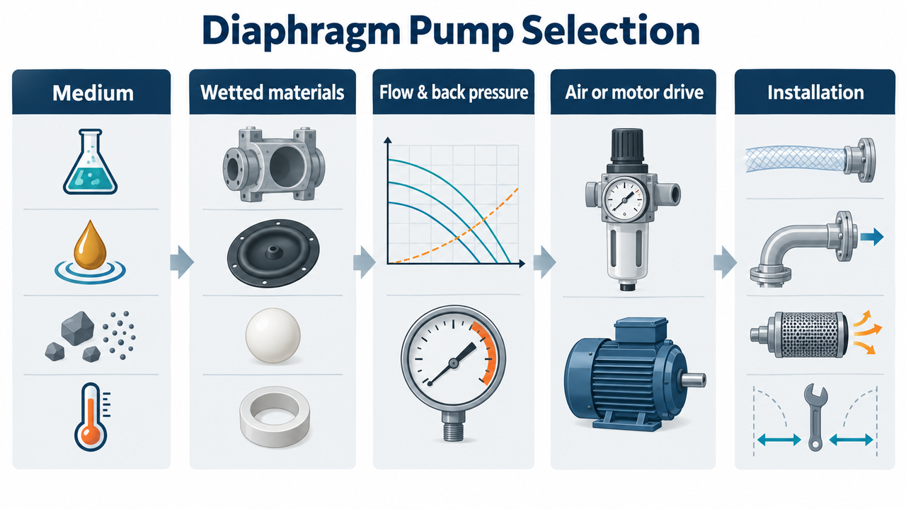
Selection should begin with the liquid and the system, then move toward a pump model. Starting with a 1-inch or 2-inch port size feels efficient, but it often hides the details that determine whether the pump will actually deliver the required duty.
Give the supplier the complete fluid description: chemical name, concentration, normal and maximum temperature, viscosity at operating temperature, solids content, particle size, fibers, abrasiveness, vapor behavior, cleaning fluid and whether the liquid can settle or crystallize during a shutdown. “Acid,” “slurry,” “solvent” and “wastewater” are labels, not usable material specifications.
Then review the full wetted path: body or liquid chamber, diaphragm, check ball or flap, seat, manifold, gaskets and any hose or fitting that remains in contact with the medium. A PP body does not make an entire pump chemically suitable by itself. Likewise, a stainless steel body does not settle the question of chloride exposure, cleaning chemistry or the elastomer selected for the diaphragm and seats.
Selection input | What it changes | Evidence to request |
Chemical composition and concentration | Wetted material and seal compatibility | Model-level wetted-material declaration and compatibility review |
Temperature range | Diaphragm, seat, gasket and body limits | Stated allowable temperature range for the quoted material set |
Viscosity and solids | Actual flow, suction behavior, check-valve response and wear | Pump curve or application confirmation at the stated medium condition |
Abrasion or fibers | Diaphragm and check-element wear, cleanout needs and flow path | Recommended check-valve arrangement, service access and spare-parts list |
Cleaning and flushing method | Chemical exposure after normal transfer and maintenance | Cleaning procedure and confirmation that all wetted materials are included |
An AODD pump's published maximum flow is a starting point, not a promise for every installation. Actual delivered flow changes with air pressure, available air volume, discharge back pressure, liquid viscosity, suction conditions, valve losses, pipe diameter, elevation and pump configuration. The same pump can behave very differently on a short, flooded water line and on a long suction hose moving a cold, viscous coating.
Ask for the performance curve and the air-consumption curve for the proposed model. Then place the intended operating point on those curves using the actual discharge pressure and medium condition. A pump sharing a compressed-air header with other equipment must be assessed at the pressure available while the rest of the system is operating, rather than at a compressor nameplate value.
This is also where pump content can become genuinely useful instead of promotional. A buyer who says “I need 50 gallons per minute” still needs to answer: at what back pressure, with what liquid, at what suction lift, through what length of hose, and for how much of the shift? Without those answers, a quoted maximum flow tells only part of the story.
Positive-displacement pumps can self-prime in many suitable applications, but that does not remove the need for disciplined suction design. Keep the suction line as short and direct as the installation allows. Avoid unnecessary restrictions, undersized fittings and air leaks. Make sure the source vessel, liquid level, temperature and vapor behavior are understood before relying on a nominal suction-lift figure.
Where downstream equipment is sensitive to uneven flow, review pulsation instead of waiting for it to become a production complaint. A pulsation dampener, pipe support, hose selection, receiver volume or a revised operating point may help, but the right solution depends on the flow profile and piping. Do not buy an accessory merely because it appears on a diagram; define the fluctuation that must be reduced and where it is causing trouble.
Air operation can be useful when compressed air is already available, when portable transfer is needed, or when the process prefers pneumatic actuation. It also introduces air-system duties: filtration where required by the selected design, pressure control, moisture management, exhaust routing, noise and possible cooling or icing during demanding operation. The pump quotation should state the required air supply, not just the liquid-side connection.
A motor-driven option can be appropriate where electrical power, a more defined drive arrangement or reduced dependence on plant air is preferred. Shinjo Pump's DBY motor-driven diaphragm pump should therefore be compared as its own configuration, with its own flow range, motor details, electrical requirements, material set and service data. Do not convert an air-pump duty into an electric-pump purchase by assuming that the word “diaphragm” makes the two interchangeable.
Two AODD quotations are comparable only when they are based on the same duty. If one supplier assumes clean water with a short flooded suction line and another assumes a viscous liquid through a long hose, the headline flow figures will not answer the same question. Ask both suppliers to state the assumed liquid, viscosity, air pressure, air consumption, discharge pressure, suction condition, wetted materials, connection standard and performance basis. Then record any exceptions next to the price.
Some AODD designs are used for deadhead-capable transfer duties because cycling can stop when liquid-side resistance reaches the available driving condition. That characteristic still needs model-level confirmation. It does not remove the need to review trapped pressure, downstream isolation, hose rating, relief philosophy or what the plant expects to happen when the discharge is closed.
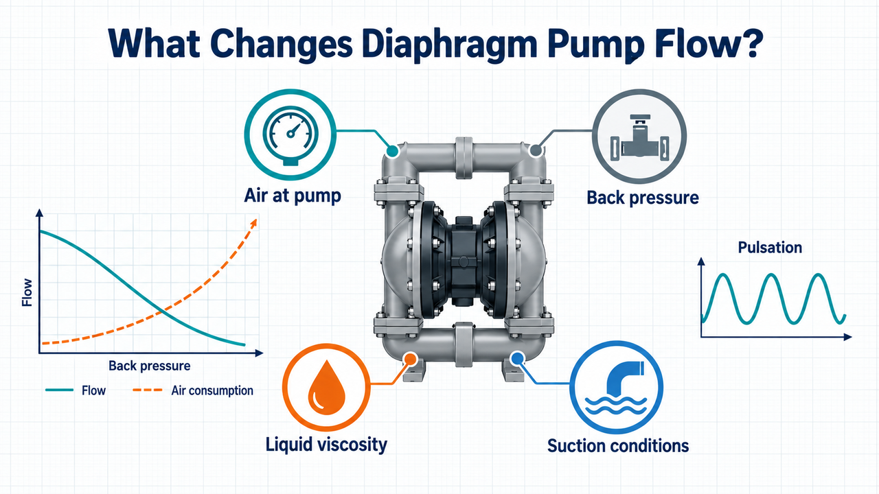
The most common disappointment with a diaphragm pump is not a broken part. It is a pump that technically runs but delivers less liquid than the operation expected. The source of that gap is usually the system around the pump.
At a given liquid duty, the air side must provide enough pressure and volume at the pump inlet. On the liquid side, the pump must overcome static lift, discharge pressure, pipe friction, fittings, control valves and the resistance of the medium itself. As viscosity increases or suction conditions worsen, the pump may cycle differently and deliver less than a water-based maximum-flow figure suggests. The correct way to evaluate this is a model-specific curve or documented application review, not a generic rule based on port size.
Pulsation belongs in the same conversation. AODD pumps discharge in alternating strokes, so they do not naturally produce the same flow pattern as a continuously rotating centrifugal pump. In some transfer jobs this is perfectly acceptable. In others, pulsation may disturb a filling operation, meter, coating process, small pipe run or downstream control valve. State whether the process can accept variation in flow and pressure. If it cannot, request a dampening and piping recommendation with the quotation.
Maximum flow normally describes one point on a performance curve under stated conditions. That figure does not automatically include a long suction hose, a partially closed discharge valve, a shared air header, cold product, added fittings, a high tank elevation or the wear that appears after sustained service. The buyer does not need to calculate every loss alone, but the supplier needs the inputs required to evaluate them.
Ask to see the curve rather than only a maximum number. On a useful curve, the liquid flow, air pressure, back pressure and air consumption can be read together. Where no curve exists for the exact medium, ask what the quoted performance is based on and what change in flow should be expected as viscosity or back pressure rises. That creates a documented assumption the commissioning team can later test.
The air line may be the hidden bottleneck. A compressor can have adequate installed capacity while pressure at the pump falls during simultaneous demand elsewhere in the plant. Long, undersized air lines, restrictions, poor drainage and contaminated air can also affect cycling. During rapid, sustained operation, expanding exhaust air may cool the air valve and surrounding equipment; cold or humid conditions deserve explicit review rather than a last-minute response to icing or slow cycling.
This does not mean every AODD installation needs a complex air-treatment package. It means the air source should be specified with the same care as the liquid line: pressure available at the pump, expected air volume, line size, quality requirement, regulation, exhaust location and operating environment.
Before releasing a purchase order, ask the following questions in sequence:
What liquid flow range is required at the actual discharge point, not only at the source tank?
What pressure must the pump overcome during normal operation and the most demanding credible condition?
What air pressure and air volume are available at the pump while other users are drawing from the same header?
What are the suction-line length, diameter, fittings, vertical lift and source-vessel conditions?
Is the medium more viscous, abrasive, volatile or temperature-sensitive than the fluid used for the published curve?
Does the downstream process need smoother flow, a specific fill time or controlled pressure?
Which parts will wear first, and can the maintenance team reach them without dismantling the surrounding system?
This check turns the phrase “diaphragm pump flow rate” into a real operating requirement. It also gives procurement a defensible basis for comparing two models that might look similar in a catalogue.
Pump selection becomes clearer when it is tied to duty rather than brand familiarity. A diaphragm pump, centrifugal pump and peristaltic pump can all move liquid, but they create flow in different ways and create different maintenance, energy and piping considerations.
Decision point | Diaphragm pump | Centrifugal pump | Peristaltic pump |
Flow pattern | Positive-displacement strokes; pulsation needs review | Typically continuous rotating flow | Positive-displacement flow with hose compression and inherent pulsation |
Difficult liquids | Can be a strong option for many viscous, solids-bearing or chemically challenging duties when configured correctly | Often best suited to cleaner, lower-viscosity liquids within the selected pump curve | Can suit certain abrasive, shear-sensitive or dosing-related duties, depending on hose and medium |
Dry-running and suction behavior | Many AODD designs are selected for tolerant transfer duties, but the exact model and medium still govern | Dry-running and priming requirements need careful review | Hose temperature, compatibility and life are central limits |
Material question | Body, diaphragms, seats and check elements all matter | Wetted casing, impeller, seal or seal-less construction matter | The hose or tube is a critical wetted component |
Best next question | Can the air, flow, materials and pulsation requirements be met together? | Can the pump meet the duty point efficiently without cavitation or seal risk? | Can the hose tolerate the chemical, pressure, temperature and expected service interval? |
For a clean-liquid process that needs steady high-volume transfer, compare a diaphragm pump with Shinjo Pump's chemical process pumps or centrifugal range before deciding. For a process dominated by viscous media, carefully compare the AODD option with the relevant screw pump range. The comparison should stay anchored to the actual process; it is not a reason to declare one pump family superior in every setting.
Choose an AODD pump when the process accepts pulsation or can manage it, compressed air is genuinely available at the required condition, and the wet-end materials suit the full liquid and cleaning cycle. It is often a credible starting point for intermittent chemical transfer, portable drum or tote handling, coatings and selected solids-bearing liquids where a conventional seal would be a concern. The decision becomes stronger when the supplier can show the performance basis at the actual viscosity and back pressure, rather than quoting a water-based maximum-flow figure.
Choose a centrifugal pump when the duty is long-running, high-volume and dominated by a clean, lower-viscosity liquid that needs a smoother flow profile. Choose a peristaltic pump when the hose is an acceptable primary wetted component and the specific chemical, pressure and service-life limits fit the process. The correct comparison is not which technology is more versatile; it is which one produces the required liquid duty with a maintainable installation and defensible operating assumptions.
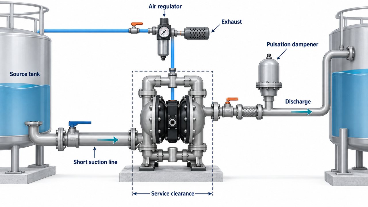
Good installation starts before the pump arrives. Make room to inspect diaphragms, check elements and the air valve. Support piping so it does not load the manifolds. Keep the suction arrangement simple. Give the exhaust a safe route. Provide isolation where maintenance needs it. The details vary by plant, but leaving all of them to a last-minute site adjustment is how a suitable pump becomes an awkward system.
Look at the installation from the maintenance technician's position. Can the source be isolated and drained? Is there enough room to remove a manifold, diaphragm or air-valve component? Will a pump failure spill retained liquid onto a walkway, electrical equipment or an inaccessible area? Are hose and pipe supports carrying their own weight rather than hanging it from the pump? These questions are routine, but they are often missed when a temporary transfer installation becomes permanent.
Where liquid can settle, plan the flush and shutdown sequence before commissioning. Where a process is batch-based, identify how the pump will be cleaned between products. Where the pump handles hazardous liquid, establish containment and response requirements with the project team. A pump is easier to maintain when the installation anticipates the normal failure modes instead of merely leaving space for a new unit.
What the operator sees | Plausible system or pump causes to investigate first | What to avoid |
Pump cycles but little liquid arrives | Empty source, suction air leak, blocked inlet, stuck check element, excessive lift or unexpected viscosity | Repeatedly increasing air pressure without checking the suction side |
Flow is lower than expected | Back pressure, restricted hose, insufficient air volume, viscous liquid, worn or contaminated check components | Treating a catalogue maximum as the guaranteed site flow |
Cycling is erratic or stops | Air-supply contamination, inadequate air pressure, air-valve issue, exhaust restriction or process-side blockage | Replacing parts before recording air and liquid conditions at the time of failure |
Discharge pressure fluctuates too much | Normal AODD pulsation amplified by piping, varying suction conditions or downstream restrictions | Adding a dampener without identifying the pressure or flow problem it must solve |
Wet-end components wear early | Abrasion, incompatible liquid, solids, crystallization, high cycle duty or unsuitable check-element material | Assuming the pump body material alone defines compatibility |
For an RFQ, provide a complete medium description, required flow range, normal and maximum discharge pressure, suction arrangement, temperature range, viscosity, solids information, available air supply or electrical supply, connection standard, installation environment, required documents, spare-parts expectations and any applicable code or certification requirement. Ask the supplier to identify the proposed body, diaphragm, check-element and seat materials individually; identify the stated performance basis; and confirm the information needed for installation and maintenance.
RFQ item | What a useful supplier response should make clear |
Liquid and cleaning media | The complete wetted-material set, including diaphragms, seats and check elements |
Flow range and discharge pressure | The expected operating point and the curve or stated basis behind it |
Air supply or electrical supply | Required pressure and air volume, or motor/electrical configuration, at the proposed duty |
Suction arrangement | Assumptions for suction lift, line length, liquid level and restrictions |
Installation environment | Connection, exhaust, access, noise, safety and any environment-specific considerations |
Maintenance expectation | Wear parts, service route, recommended spares and documents supplied with the order |
The table is not paperwork for its own sake. It prevents a supplier from quoting a material combination that suits a different liquid, or a flow figure that assumes a different air and piping system. A duty that changes after start-up should be reassessed from the same data rather than guessed from port size or pump appearance.
Many air-operated double diaphragm pumps are selected for duties that involve dry running, but this is not a universal permission. The exact pump design, diaphragm material, air valve, medium, temperature and expected run time still need confirmation from the model documentation.
It may be suitable for many viscous liquids, but viscosity reduces flow and can make suction conditions more demanding. State viscosity at operating temperature, desired flow, suction arrangement and discharge pressure so the supplier can assess the actual duty.
Rated flow is normally tied to stated test conditions. Back pressure, available air volume, air pressure at the pump, viscosity, suction restrictions, lift, piping losses and the condition of check components can all reduce delivered flow in service.
Neither is inherently better. Choose an AODD pump when the process and available compressed air suit pneumatic transfer. Compare a motor-driven diaphragm pump when electrical drive, a different installation arrangement or less dependence on plant air is more appropriate. Review the quoted model rather than deciding from the word “diaphragm.”
Choose a diaphragm pump because it fits a defined transfer duty: the liquid needs a separated drive side, the expected flow and pressure can be met with the available air or motor drive, the complete wetted-material set is suitable, and the piping can tolerate or manage pulsation. Do not choose it merely because it has the right connection size or a familiar maximum-flow number. The most reliable purchase is the one whose curve, materials, air supply, installation and service plan all describe the same operating condition.
